Air Conditioning System: Automatic Type 7B-53
DTC B1511: Temperature Control Actuator (Position Sensor) and/or Its Circuit Malfunction
S7RS0B7224013
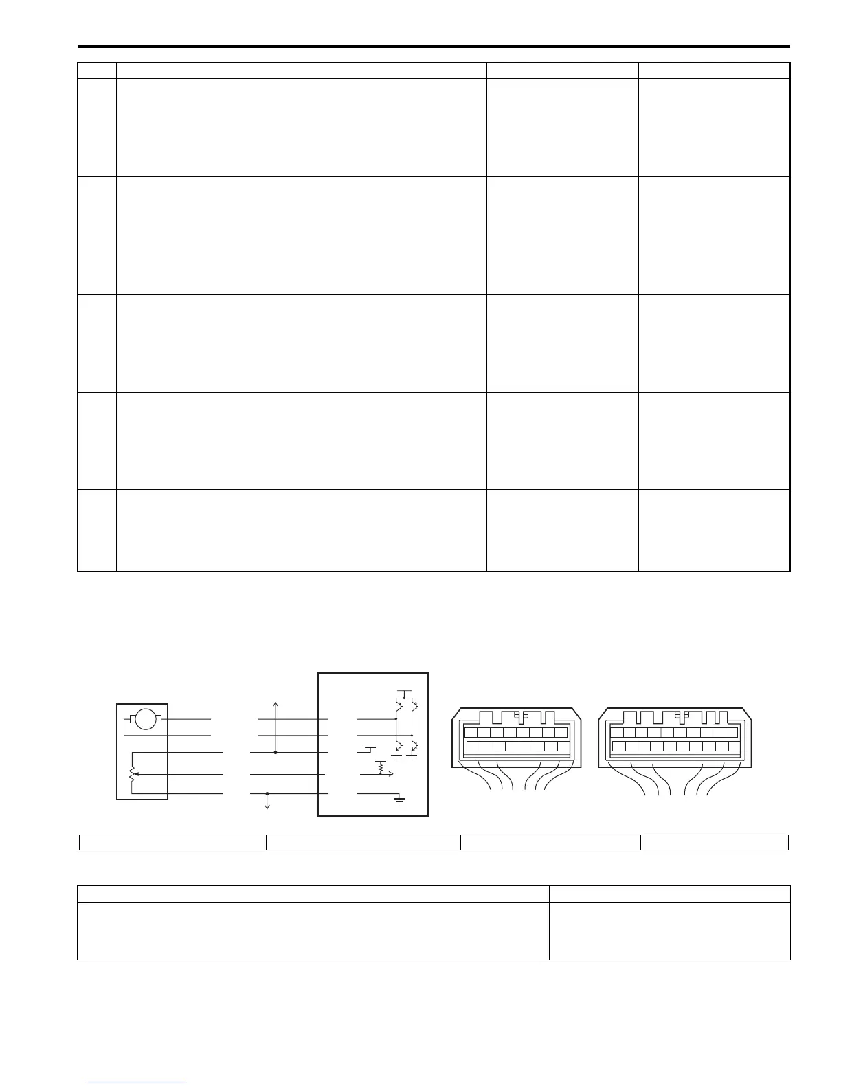
Wiring Diagram
DTC Detecting Condition and Trouble Area
4 Sunload sensor power supply circuit check
1) Measure voltage between “PNK” wire terminal of
sunload sensor connector and vehicle body ground with
ignition switch turned ON.
Is voltage 0 V?
Go to Step 5. “PNK” wire shorted to
other circuit.
5 Sunload sensor signal circuit check
1) Disconnect HVAC control module connector with ignition
switch turned OFF.
2) Measure resistance between “YEL/BLK” wire terminal of
sunload sensor connector and vehicle body ground.
Is resistance infinity?
Go to Step 6. “YEL/BLK” wire shorted
to ground circuit.
6 Sunload sensor signal circuit check
1) Measure resistance between “G52-5” terminal of HVAC
control module connector and “YEL/BLK” wire terminal
of sunload sensor connector.
Is resistance below 5
Ω
?
Go to Step 7. “YEL/BLK” wire open or
high resistance circuit.
7 Sunload sensor signal circuit check
1) Measure voltage between “YEL/BLK” wire terminal of
sunload sensor connector and vehicle body ground with
ignition switch turned ON.
Is voltage 0 V?
Go to Step 8. “YEL/BLK” wire shorted
to other circuit.
8 Sunload sensor check
1) Check sunload sensor referring to “Sunload Sensor
Inspection”.
Is it in good condition?
HVAC control module
faulty.
Sunload sensor faulty.
Step Action Yes No
78
12
910
65 43
1516 14 13 12 11
G52
78
910
1920
12
1112
65 43
1718 16 15 14 13
G51
M
12V
5V
5V
YEL
WHT
GRY/BLU
GRY/RED
2
1
ORN
G51-3
G51-4
G52-1
G52-13
G52-3
3
4
I5RS0A722013-01
1. HVAC control module 2. Temperature control actuator 3. To air flow control actuator 4. To other sensors
DTC Detecting Condition Trouble Area
Temperature control actuator position sensor signal voltage is higher than or
lower than specified value for specified time continuously.
• Temperature control actuator circuit
• Temperature control actuator
• HVAC control module

 Loading...


