5A-52 Automatic Transmission/Transaxle:
DTC P0722: Output Speed Sensor Circuit No Signal
S7RS0B5104028
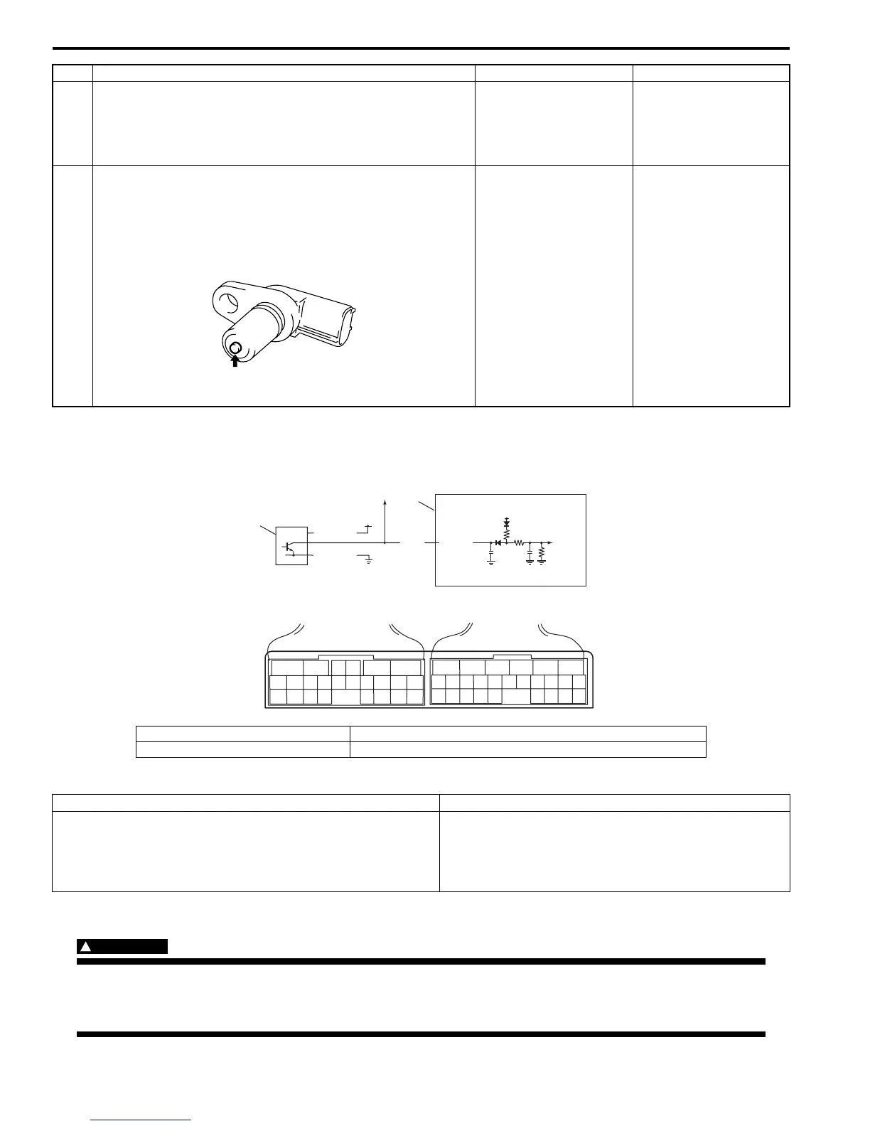
Wiring Diagram
DTC Detecting Condition and Trouble Area
DTC Confirmation Procedure
WARNING
!
• When performing a road test, select a place where there is no traffic or possibility of a traffic
accident and be very careful during testing to avoid occurrence of an accident.
• Road test should be carried out with 2 persons, a driver and a tester, on a level road.
3 Inspect input shaft speed sensor
1) Inspect input shaft speed sensor referring to “Input Shaft
Speed Sensor Inspection”.
Is result satisfactory?
“WHT” or “BLK” circuit
open or short.
Replace input shaft
speed sensor.
4 Check visually input shaft speed sensor and direct
clutch drum for the following
• No damage
• No foreign material attached
• Correct installation
Are they in good condition?
Intermittent trouble or
faulty TCM.
Check for intermittent
referring to “Intermittent
and Poor Connection
Inspection in Section
00”.
If OK, substitute a
known-good TCM and
recheck.
Clean, repair or replace.
Step Action Yes No
I2RH0B510020-01
1. TCM 3. To ECM
2. Output shaft speed sensor [A]: Terminal arrangement of TCM connector (viewed from harness side)
DTC detecting condition Trouble area
No output shaft speed sensor signal is detected although
input shaft speed sensor signals are detected while vehicle is
running at 5 km/h (3 mile/h) or more in vehicle speed with
“D”, “2” or “L” range.
• Output shaft speed sensor or its circuit malfunction
• Damaged sensor gear (driven gear)
• Damaged output shaft speed sensor drive gear
•TCM
IG1
12V
PPL
C35-25
2
C34
25
C35
[A]
1
BLK/RED
BLK/ORN
3
I4RS0B510005-01

 Loading...


