4E-25 ABS:
DTC U1073: Control Module Communication Bus Off
S7RS0B4504018
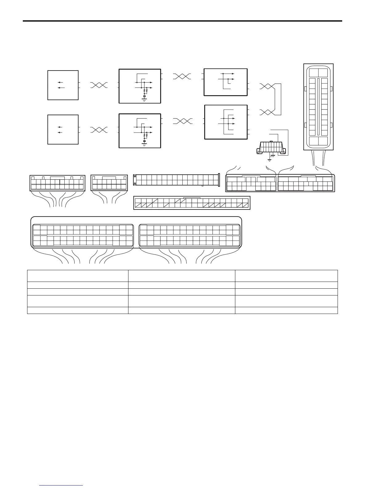
Wiring Diagram
DTC Detecting Condition
Transmission error that is inconsistent between transmission data and transmission monitor (CAN bus monitor) data is
detected more than 7 times continuously.
RED
WHT
E03-6
E03-12
1
4
7
RED
WHT
2
[C]
[B]
G37
E46
1234567
1234567
891011
891011
121314
121314
151617
18
19202122
[E]
65
161514131211
43
2423 2122
10 9 8 7
21
1920 1817
C34
1716
26
25
1514
65 342
1312
232224
1110 9
212019
87
18
1
C35
[F]
RED
WHT
C37-13
C37-12
RED
WHT
C34-17
C34-7
3
1234567891011141516
36 34 33 32 31 30 29 24 2337
181920
[D]
[A]
G49
E23-3
E23-18
5
RED
WHT
G28-7
G28-9
RED
WHT
G49-19
G49-18
6
RED
WHT
E03-10
E03-8
G37-4
G37-2
RED
WHT
E46-1
E46-2
RED
WHT
RED
WHT
G28-8
G28-10
RED/BLK
WHT/BLK
G37-3
G37-1
E03
15
16
17
18
19
20
21
22
23
24
25
2
3
4
5
6
7
8
9
10
11
12
1
13
14
26
E23
C37
34
1819
5671011
17
20
47 46
495051
2122
52
16
25
9
24
14
29
5557 54 53
59
60
58
2
262728
15
30
56
48
32 31
343536374042 39 38
44
45
43 41 33
1
1213
23
8
34
1819
5671011
17
20
47 46
495051
2122
52
16
25
9
24
14
29
5557 54 53
59
60 58
2
262728
15
30
56
48
32 31
343536374042 39 38
44
45
43 41 33
1
1213
23
8
G28
1234567
8
910111213141516
1718
19
20
212223242526272829303132
I6RS0C450015-01
[A]: ABS control module connector (viewed from
terminal side)
[F]: Keyless start control module connector
(viewed from harness side)
5. Combination meter
[B]: BCM connector (viewed from harness side) 1. ABS hydraulic unit / control module assembly 6. Keyless start control module (if equipped)
[C]: ECM connector (viewed from harness side) 2. ECM 7. Data link connector (DLC)
[D]: Combination meter connector (viewed from
harness side)
3. TCM
[E]: TCM connector (viewed from harness side) 4. BCM

 Loading...


