8B-64 Air Bag System:
NOTE
Upon completion of inspection and repair work, perform the following items.
• Reconnect all air bag system components and ensure all components are properly mounted.
• Clear DTCs referring to “DTC Clearance”, if any.
• Repeat “Air Bag Diagnostic System Check” to confirm that the trouble has been corrected.
DTC B1061 / B1065: Driver / Passenger Side-Air Bag Initiator Circuit Resistance High
S7RS0B8204030
Wiring Diagram
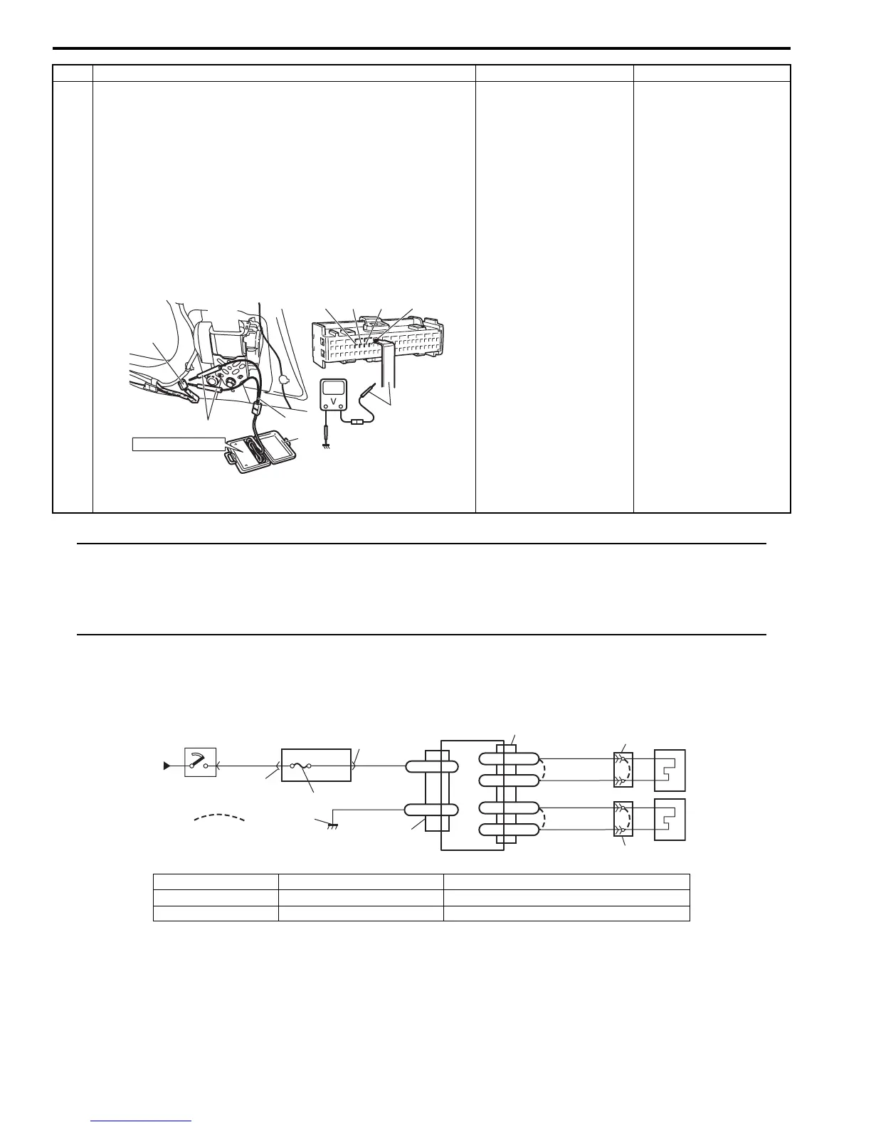
2 1) With ignition switch OFF, disconnect special tools (A),
(B) and (C) and SDM connector.
2) Release shorting bar in SDM connector inserting release
tool (1) included in special tool (A).
3) Measure voltage between “L29-7” and body ground, and
between “L29-8” and body ground (for DTC B1054) or
between “L29-9” and body ground, and between “L29-
10” and body ground (for DTC B1058).
Special tool
(A): 09932-76010
With ignition switch ON, is voltage 1 V or less?
Substitute a known-
good SDM and recheck.
DTC B1054: “GRN/
ORN” circuit or “GRN/
YEL” circuit shorted to
power supply circuit.
DTC B1058: “BLU/
ORN” circuit or “BLU/
YEL” circuit shorted to
power supply circuit.
Step Action Yes No
"L29-8" "L29-9" "L29-10""L29-7"
(A)
STEERING WHEEL
(B)
(C)
(A)
"L10", "L36"
I7RS0A820019-02
1
2
3
GRN
RED
8
BLK
L29-27
L29-28
IG
E1
4
“L29”
“L04”
“G32”
“L29”
L29-12
DS+
L29-11
DS-
GRY
GRY/RED
5
6
“L25”
L29-13
PS+
L29-14
PS-
BRN
BRN/WHT
7
“L30”
[A]
I7RS0A820020-04
[A]: Shorting bar 3. “A/BAG” fuse 6. Driver side-air bag (inflator) module
1. From main fuse 4. Junction block assembly 7. Passenger side-air bag (inflator) module
2. Ignition switch 5. SDM 8. Ground for air bag system

 Loading...


