Power Assisted Steering System: 6C-17
DTC C1113: Steering Torque Sensor (Main and Sub) Circuit Correlation
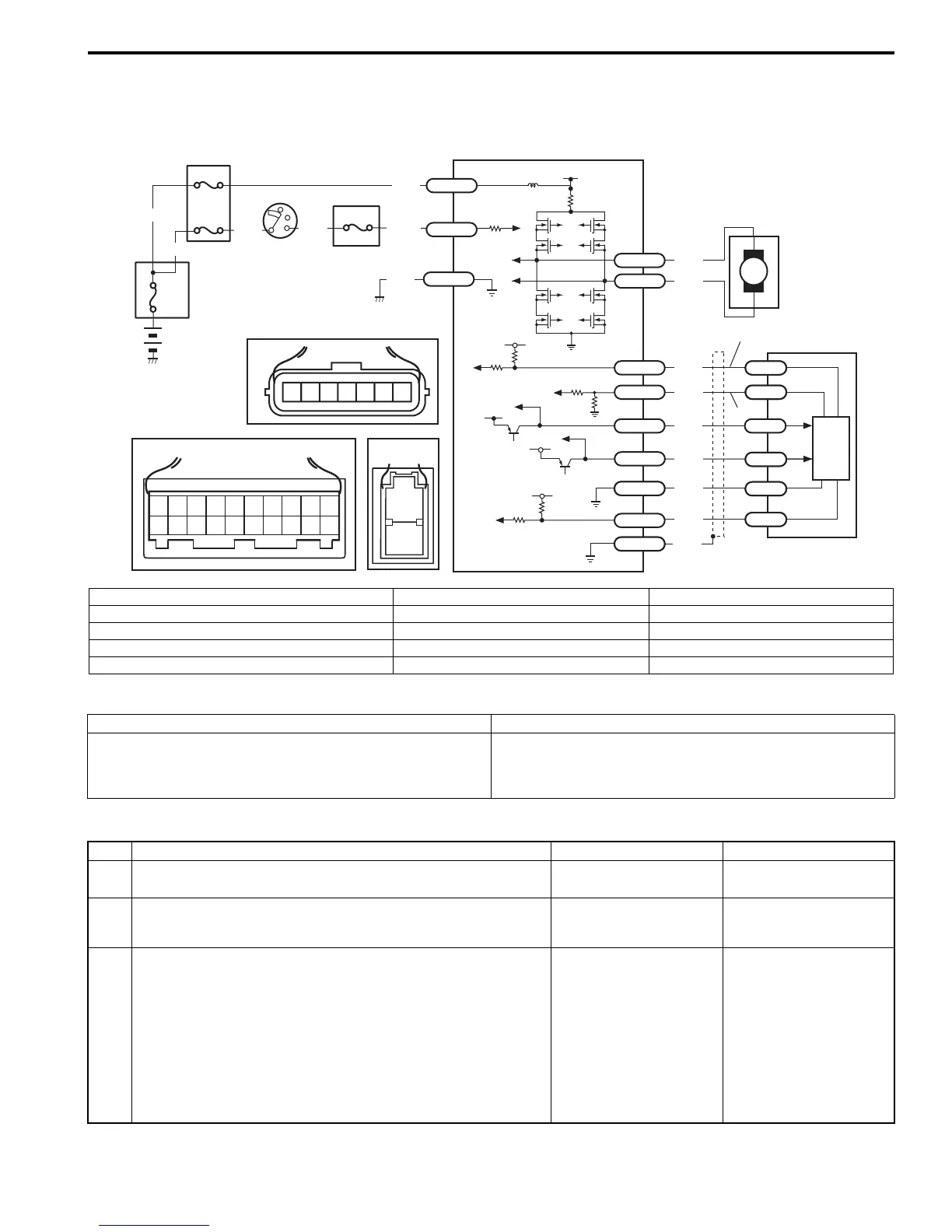
S7RS0B6304012
Wiring Diagram
DTC Detecting Condition and Trouble Area
DTC Troubleshooting
M
5V
BLK
RED
WHT
BLU
GRN
BRN
YEL
E51-1
E51-2
E52-18
E53-5
E53-7
E52-6
E52-8
E53-2
E52-9
E52-16
E52-19
GRY
[A]
12
3
4
5
67
8
9
11
10
12 13
14
15
16
17 18 19
20
5
6
7
12V
5V
5V
12V
RED
E52-20
E53-6
E53-4
E53-1
10
9
1
2
[B]
[C]
7654321
LT GRN
/BLK
E52-1
E49-1
GRN
GRN
WHT
BLK
WHY
8
3
4
4
4
4
1
2
E49-2
BLK
I7RS0B630005-01
[A]: Connector “E52” (viewed from harness side) 3. Junction block assembly 8. Individual circuit fuse box No.1
[B]: Connector “E49” (viewed from harness side) 4. Fuse 9. Torque sensor signal (sub) circuit
[C]: Connector “E53” (viewed from harness side) 5. P/S control module 10. Torque sensor signal (main) circuit
1. Main fuse box 6. Torque sensor
2. Ignition switch 7. Torque sensor amplifier
DTC detecting condition Trouble area
Voltage difference between torque sensor main signal and
sub signal is more than 0.6 V for 1 second continuously
(1 driving cycle detection logic)
• Torque sensor signal circuit
• Torque sensor
• P/S control module
Step Action Yes No
1 Was “EPS System Check” performed? Go to Step 2. Go to “EPS System
Check”.
2 DTC check
Is DTC C1114 and/or DTC C1119 indicated together?
Go to applicable diag.
flow.
Go to Step 3.
3 Torque sensor signal (sub) circuit check
1) Check for P/S control module connector (“E52”) for
proper connection.
2) With ignition switch turned OFF, disconnect torque
sensor connector.
3) Check for voltage between “E53-7” (“BLU” wire) terminal
and body ground with ignition switch ON.
Is it about 5 V?
Go to Step 4. Go to Step 7.

 Loading...


