1A-48 Engine General Information and Diagnosis:
Troubleshooting
NOTE
When measuring circuit voltage, resistance and/or pulse signal at ECM connector, connect the special
tool to ECM and/or the ECM connectors referring to “Inspection of ECM and Its Circuits”.
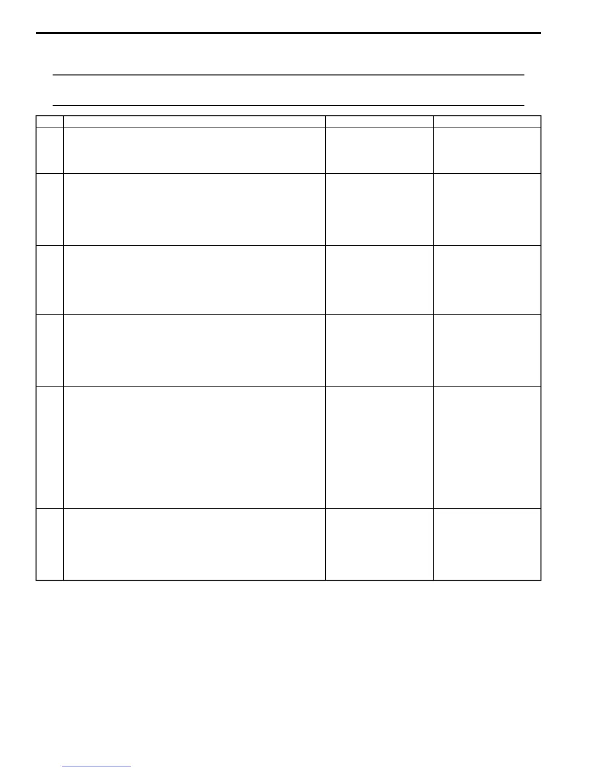
Malfunction Indicator Lamp Remains ON after Engine Starts
S7RS0B1104012
Wiring Diagram and Circuit Description
Refer to “MIL Does Not Come ON with Ignition Switch ON and Engine Stop (but Engine Can Be Started)”.
Step Action Yes No
1 MIL power supply check
1) Turn ignition switch to ON position.
Do other warning lights come ON?
Go to Step 2. Go to Step 3.
2 DTC check
1) Connect scan tool to DLC with ignition switch turned
OFF.
2) Turn ON ignition switch and check DTC.
Is there DTC(s) P1674, P1676, P1678 and/or P1685?
Go to applicable DTC
diag. flow.
Substitute a known-
good combination meter
and recheck. If MIL still
remains OFF, substitute
a known-good ECM and
recheck.
3 CAN communication line circuit check
1) Check CAN communication circuit between combination
meter and ECM, TCM (A/T model) referring to Step 3 of
“DTC P1674: CAN Communication (Bus Off Error)”
Is circuit in good condition?
Go to Step 4. Repair or replace.
4 “METER” fuse check
1) Turn ignition switch to OFF position.
2) Check for fuse blown at “METER” fuse in junction block
assembly.
Is “METER” fuse in good condition?
Go to Step 5. Replace “METER” fuse
and check for short.
5 Combination meter power supply check
1) Remove combination meter referring to “Combination
Meter Removal and Installation in Section 9C”.
2) Check for proper connection to combination meter
connector at “G28-31” and “G28-16” terminals.
3) If OK, then turn ignition switch to ON position and
measure voltage between combination meter connector
at “G28-31” terminal and vehicle body ground.
Is it 10 – 14 V?
Go to Step 6. “RED/BLK” wire is open
circuit.
6 Combination meter circuit check
1) Turn ignition switch to OFF position.
2) Measure resistance between “G28-16” terminal of
combination meter connector and vehicle body ground.
Is resistance 1
Ω
or less?
Substitute a known-
good combination meter
and recheck. If MIL still
remains OFF, substitute
a known-good ECM and
recheck.
“BLK/ORN” wire is open
or high resistance
circuit.

 Loading...


