Electronic Stability Program: 4F-41
DTC C1057: ESP® Control Module Power Supply Circuit Failure
S7RS0B4604053
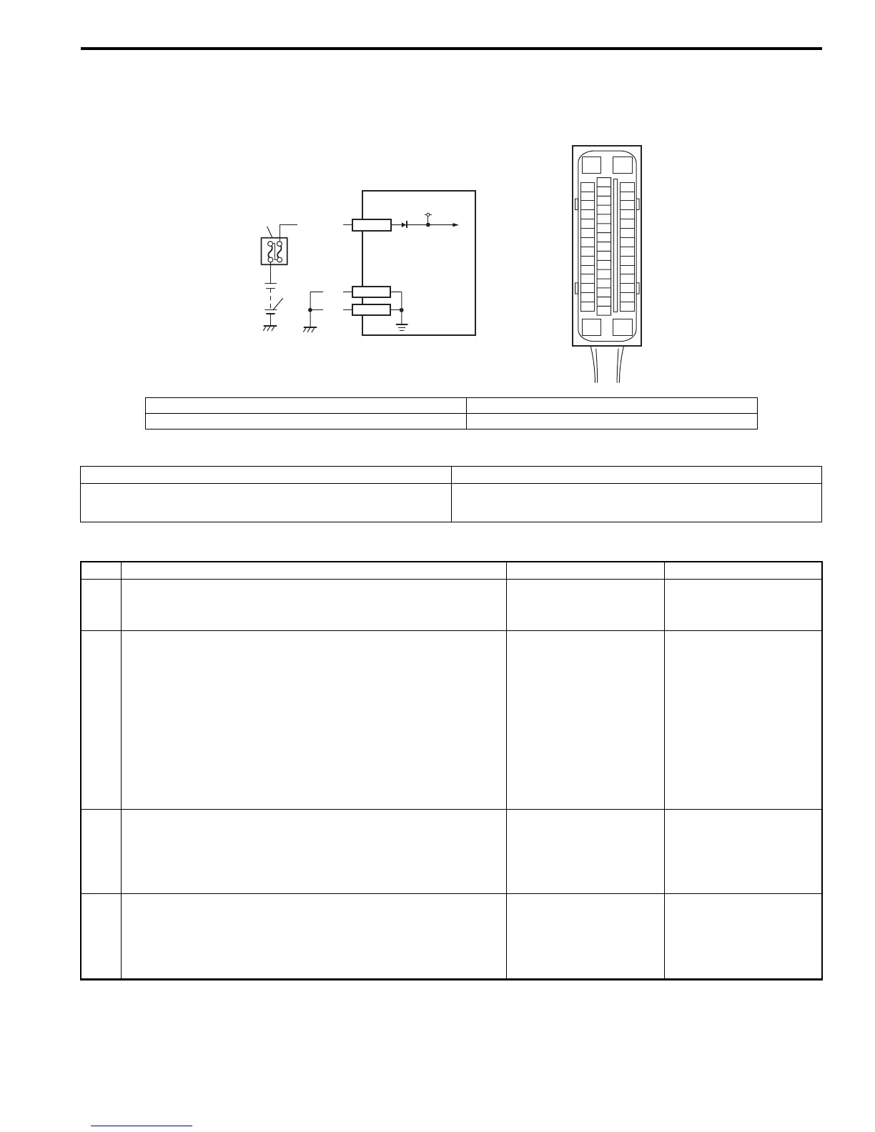
Wiring Diagram
DTC Detecting Condition and Trouble Area
DTC Troubleshooting
[A]
E85
16
1
15
2
3
4
5
6
7
8
9
10
11
12
13
14
17
18
19
20
21
22
23
24
25
26
27
28
29
30
31
32
33
34
35
36
37
38
39
40
41
42
43
44
45
46
47
WHT/BLU
1
2
3
12V
E85-1
BLK
E85-16
E85-47
BLK
I6RS0B460023-02
[A]: ESP® control module connector (viewed from terminal side) 2. Main fuse box
1. Battery 3. ESP® hydraulic unit / control module assembly
DTC Detecting Condition Trouble Area
• ESP® control module power supply voltage is too high.
• ESP® control module power supply voltage is too low.
• ESP® control module power supply circuit
• ESP® control module
Step Action Yes No
1 Was “Electronic Stability Program Check” performed? Go to Step 2. Go to “Electronic
Stability Program
System Check”.
2 Check power supply circuit from battery
1) Disconnect ESP® hydraulic unit / control module
connector with ignition switch turned OFF.
2) Check for proper connection to ESP® control module
connector at terminals “E83-1”, “E85-16” and “E85-47”.
3) If OK, then turn ignition switch to ON position and
measure voltage between terminals “E85-1” and “E85-
16”, “E85-47”.
Are voltage 9.7
±
0.3 V or more?
Go to Step 5. Go to Step 3.
3 Check ESP® control module ground circuit
1) Measure resistance between each terminal of “E85-16”,
“E85-47” and vehicle body ground.
Is resistance less than 2
Ω
?
Go to Step 4. “BLK” wire circuit in
open or high resistance.
4 Check power supply circuit from battery
1) Measure voltage between positive battery terminal and
vehicle body ground with engine running.
Is voltage 9.7
±
0.3 V or more?
Imperfect short between
“WHT/BLU” wire circuit
and vehicle body
ground.
Check charging system
referring to “Generator
Test (Undercharged
Battery Check) in
Section 1J”.

 Loading...


