7B-32 Air Conditioning System: Manual Type
Relief Valve Removal and Installation
S7RS0B7216030
Removal
1) Recover refrigerant from the A/C system with
recovery and recycling equipment referring to
“Recovery” in “Operation Procedure for Refrigerant
Charge”.
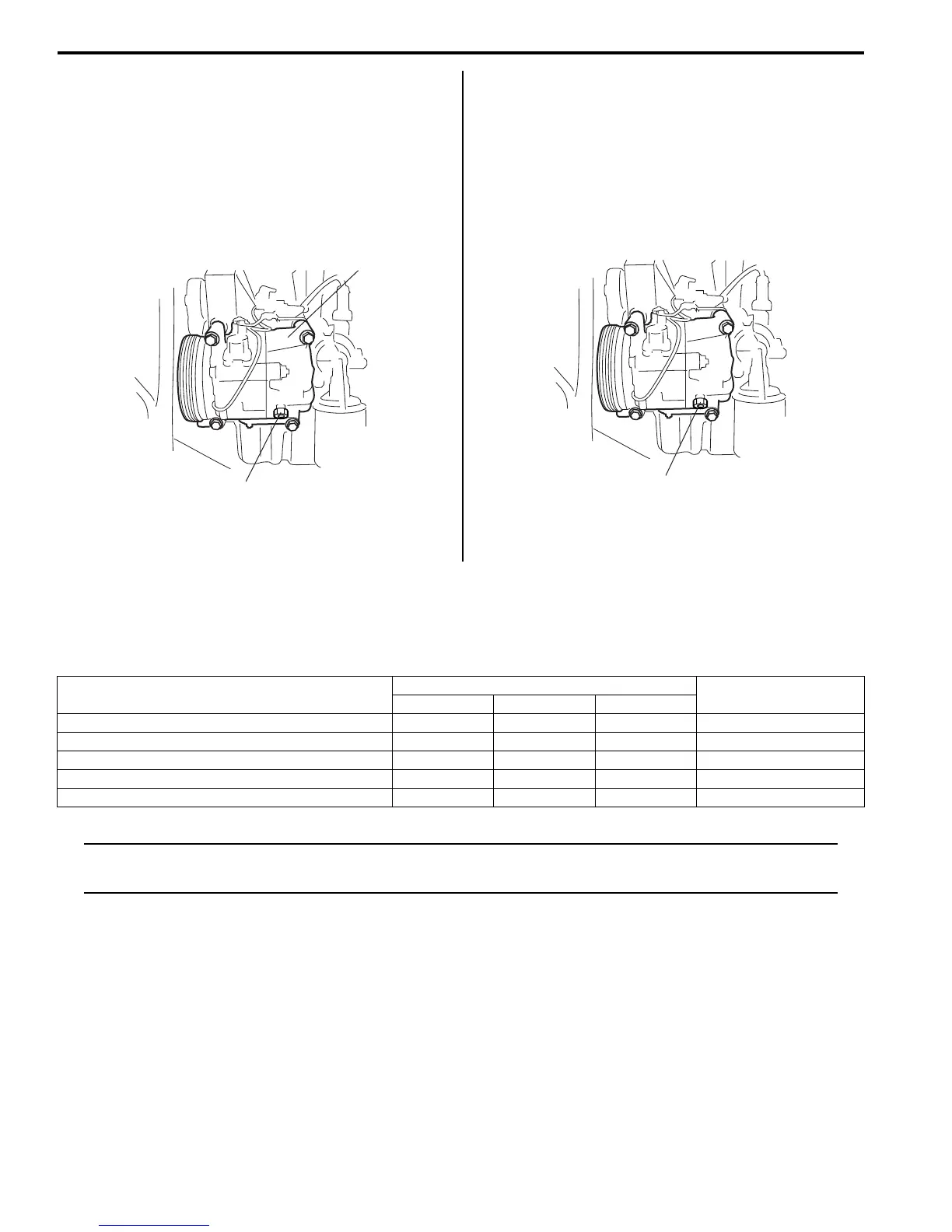
2) Remove relief valve (1) from compressor (2).
Installation
Reverse removal procedure nothing the following
instructions.
• Use new O-ring.
• Apply compressor oil to O-ring.
• Tighten relive valve to the specified torque.
Tightening torque
Relief valve (a): 8 N·m (0.8 kgf-m, 6.0 lb-ft)
• Evacuate and charge the A/C system referring to
“Evacuation” and “Charge” in “Operation Procedure
for Refrigerant Charge”.
Specifications
Tightening Torque Specifications
S7RS0B7217001
NOTE
The specified tightening torque is also described in the following.
“Compressor Assembly Components”
Reference:
For the tightening torque of fastener not specified in this section, refer to “Fasteners Information in Section 0A”.
1
2
I4RS0A720048-01
(a)
I4RS0A720049-01
Fastening part
Tightening torque
Note
N⋅mkgf-mlb-ft
Receiver/dryer bolt 10 1.0 7.5 )
Expansion valve mount bolt 3.5 0.35 2.5 )
A/C refrigerant pressure sensor 11 1.1 8.0 )
Armature plate bolt 15 1.5 11.0 )
Relief valve 8 0.8 6.0 )

 Loading...


