ABS: 4E-22
DTC C1061: ABS Pump Motor and/or Motor Driver Circuit
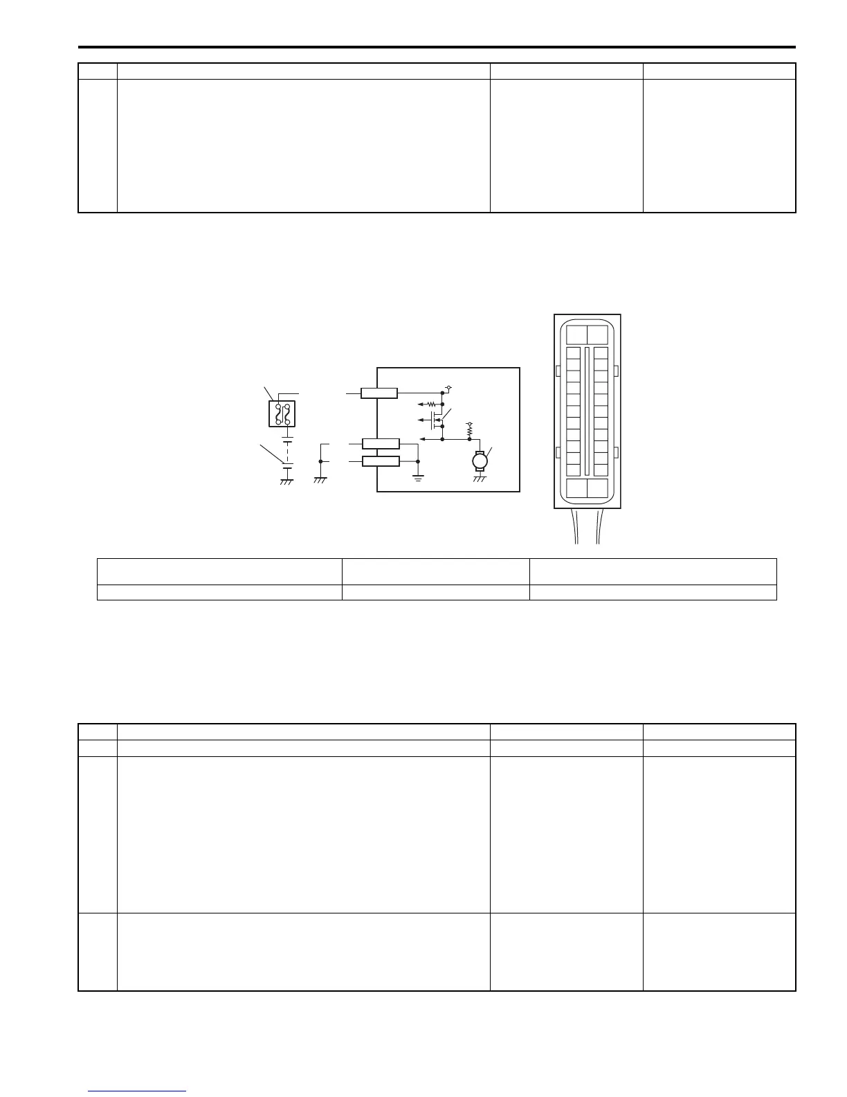
S7RS0B4504015
Wiring Diagram
DTC Detecting Condition
The ABS control module monitors the voltage at monitor terminal of pump motor circuit constantly with the ignition
switch turned ON. It sets this DTC when the voltage at the monitor terminal does not become high / low according to
ON/OFF commands to the motor driver (transistor) of the module (does not follow these commands).
DTC Troubleshooting
5 1) Measure voltage between terminals “E03-14” and “E03-
13” with engine running.
Is voltage 18
±
1.0 V or less?
Poor connection of
“E03-14” and/or “E03-
13” terminals. If the
terminals are in good
condition, substitute a
known-good ABS
hydraulic unit / control
module and recheck.
Check charging system
referring to “Generator
Test (Overcharged
Battery Check) in
Section 1J”.
Step Action Yes No
WHT/RED
1
2
5
BLK
BLK
E03-13
E03-26
[A]
E03
15
16
17
18
19
20
21
22
23
24
25
2
3
4
5
6
7
8
9
10
11
12
1
13
14
26
M
3
4
E03-1
12V
12V
I6RS0C450012-01
[A]: ABS hydraulic unit / control module connector
(viewed from terminal side)
2. Main fuse box 4. ABS pump motor
1. Battery 3. Pump motor driver (transistor) 5. ABS hydraulic unit / control module assembly
Step Action Yes No
1 Was “ABS Check” performed? Go to Step 2. Go to “ABS Check”.
2 1) Turn Ignition switch to OFF position.
2) Disconnect ABS hydraulic unit / control module
connector.
3) Check for proper connection to ABS hydraulic unit /
control module connector at terminal “E03-1”.
4) If OK, then measure voltage between terminal “E03-1” of
module connector and body ground.
Is it 10 – 14 V?
Go to Step 3. “WHT/RED” circuit
open.
3 Measure resistance between terminal “E03-13” and “E03-
26” of ABS hydraulic unit / control module connector and
body ground.
Is resistance less than 1
Ω
?
Substitute a known-
good ABS hydraulic unit
/ control module
assembly and recheck.
Ground circuit for ABS
hydraulic unit / control
module open or high
resistance.

 Loading...


