Power Assisted Steering System: 6C-47
P/S Motor and Its Circuit Inspection
S7RS0B6306013
1) Remove console box.
2) Disconnect motor connector (“E51”) from P/S control
module with ignition switch OFF.
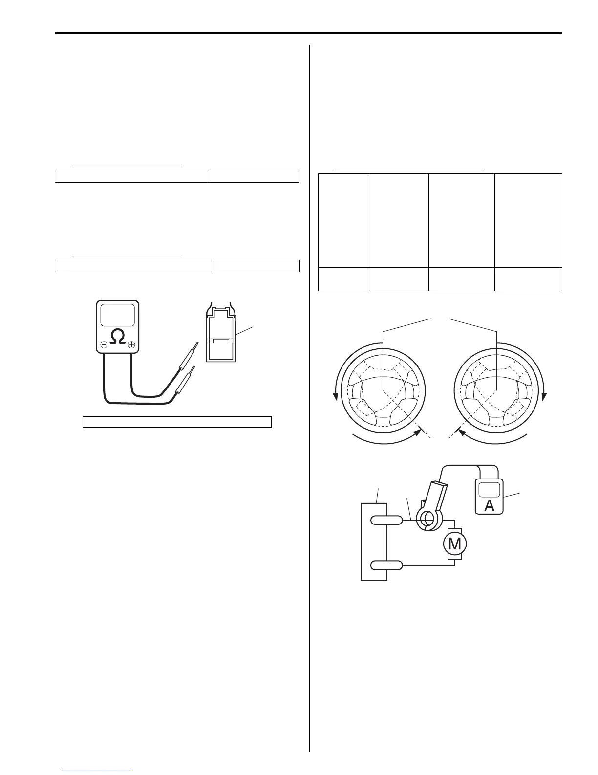
3) Check for resistance between terminals of motor
connector (“E51”).
If check result is not as specified, replace steering
gear case assembly.
Motor circuit resistance
4) Check for continuity between terminal of motor
connector (“E51”) and body ground.
If check result is not as specified, replace steering
gear case assembly.
Motor circuit resistance
5) Hoist vehicle.
6) Connect “E51” connector to P/S control module with
ignition switch OFF position.
7) Using ammeter (2), check that P/S motor (1) current
is as following table with idling engine. If check result
is not satisfactory, check P/S control module
referring to “Inspection of P/S Control Module and Its
Circuits”. If OK, replace steering gear case
assembly.
Motor current at hoisted vehicle
“E51-1” and “E51-2” (For motor) About 1 Ω
“E51-2” and body ground No continuity
1. Connector “E51” (viewed from harness side)
E51
1
1
2
I6RS0C630025-01
Condition
When
steering
wheel is left
at straight
position: [A]
When
steering
wheel is
turned left or
right by
turning
speed with
90° /sec: [B]
When
steering
wheel is kept
fully turned
left or right
until it stops.:
[C]
Motor
current
Approx. 0 A
Approx.
0 – 4 A
Approx.
30 – 45 A
1
3
2
E51-1
E51-2
[C]
[A]
[B] [B]
I6RS0C630022-01

 Loading...


