Engine General Information and Diagnosis: 1A-205
A/C System Circuits Check
S7RS0B1104084
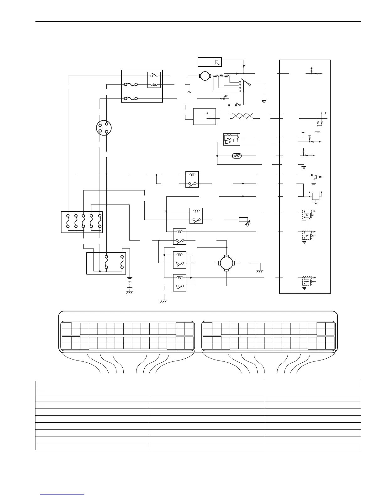
Wiring Diagram
E23 C37
34
1819
5671011
1720
47 46495051
2122
52
1625
9
24
14
29
5557 54 53
59
60 58
2
262728
15
30
56 48
32 31343536374042 39 38
44
45 43 41 33
11213
23
834
1819
5671011
1720
47 46495051
2122
52
1625
9
24
14
29
5557 54 53
59
60 58
2
262728
15
30
56 48
32 31343536374042 39 38
44
45 43 41 33
11213
23
8
BLK/REDBLK/RED
BLK/YEL BLK/YEL
BLK/YEL
BRN/WHT
12V
5V
12
E23-1
E23-60
BLK/RED
LT GRN
BLK/RED
E23-16
E23-46
L+
L–
H–
H
+
BLU/RED
BLK
BLUWHT
BLK
BLU/BLK
BLU/RED
GRN
GRY
E23-48
8
11
2
3
BLU/WHT
RED
WHT
RED
WHT
E23-3
E23-18
E23-19
6
BLK
WHT
BLK
12V
E23-47
GRY
WHT
YEL
BLU
WHT
BLK/YEL
RED/BLK
GRN/WHT
WHT/BLU
1
7
13
14
5V
5V
4
E23-55
C37-14
GRY/RED
RED
E23-54
ORN
5V
E23-57
WHT/BLK
16
9
10
25
17
5
24
15
22
BLU/YEL
23212019
GRN
BLK
18
26
28
27
I6RS0C110042-01
1. Blower fan motor 11. Radiator cooling fan motor 21. “A/C COMP” fuse
2. Blower fan switch 12. Main relay 22. “IG ACC” fuse
3. A/C switch 13. ECM 23. “RDTR FAN” fuse
4. A/C refrigerant pressure sensor 14. Ignition switch 24. Junction block assembly
5. Blower motor relay 15. BCM 25. “IG2 SIG” fuse
6. Compressor relay 16. Evaporator outlet air temp. sensor 26. HVAC control module
7. A/C compressor 17. “BACK” fuse 27. For manual A/C
8. Radiator cooling fan relay No.1 18. Individual circuit fuse box No.1 28. For automatic A/C
9. Radiator cooling fan relay No.2 19. “HTR FAN” fuse
10. Radiator cooling fan relay No.3 20. “FI” fuse

 Loading...


