Engine General Information and Diagnosis: 1A-69
DTC P0111: Intake Air Temperature Sensor 1 Circuit Range / Performance
S7RS0B1104023
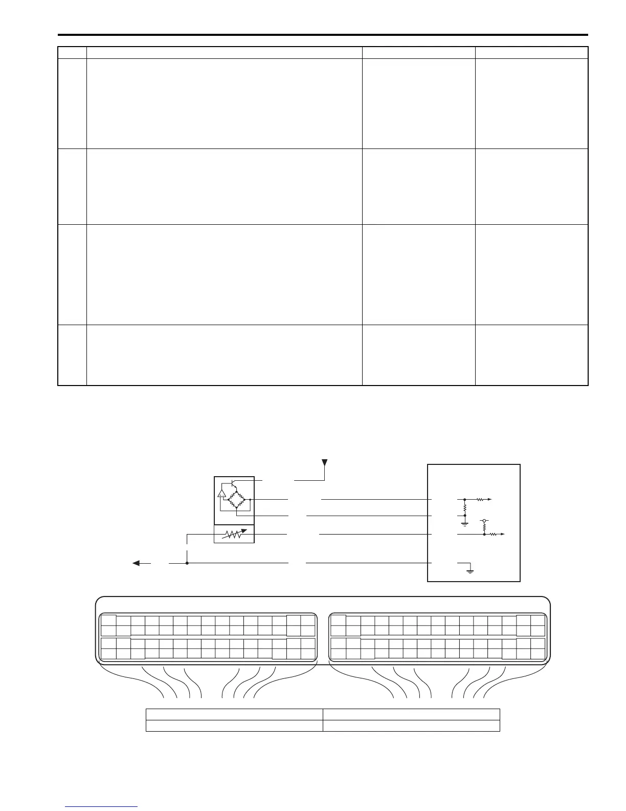
Wiring Diagram
6 Ground circuit check
1) Measure resistance between “C37-55” terminal of ECM
connector and vehicle body ground.
Is resistance below 5
Ω
?
“ORN” wire is open or
high resistance circuit.
ECM grounds “E23-31”,
“C37-58”, “C37-15” and/
or “C37-30” circuit are
open or high resistance.
If wires are OK,
substitute a known-
good ECM and recheck.
7 MAP sensor signal circuit check
1) Turn ON ignition switch.
2) Measure voltage between “RED/BLK” wire terminal of
MAP sensor connector and engine ground.
Is voltage 4 – 6 V?
Go to Step 9. Go to Step 8.
8 MAP sensor signal circuit check
1) Disconnect connectors from ECM with ignition switch
turned OFF.
2) Measure resistance between “RED/BLK” wire terminal of
MAP sensor connector and “C37-53” terminal of ECM
connector.
Is resistance below 2
Ω
?
“RED/BLK” wire is
shorted to power supply
circuit.
“RED/BLK” wire is open
or high resistance
circuit.
9 MAP sensor output signal check
1) Check MAP sensor according to “MAP Sensor
Inspection in Section 1C”.
Is it in good condition?
Substitute a known-
good ECM and recheck.
Faulty MAP sensor.
Step Action Yes No
E23 C37
34
1819
5671011
1720
47 46495051
2122
52
1625
9
24
14
29
5557 54 53
59
60 58
2
262728
15
30
56 48
32 31343536374042 39 38
44
45 43 41 33
11213
23
834
1819
5671011
1720
47 46495051
2122
52
1625
9
24
14
29
5557 54 53
59
60 58
2
262728
15
30
56 48
32 31343536374042 39 38
44
45 43 41 33
11213
23
8
5V
2
BLK/YEL
GRY/BLU
GRY
ORN
1
GRN/BLK
C37-25
C37-55
3
4
ORN
C37-26
C37-27
BLK/RED
I4RS0B110018-01
1. MAF and IAT sensor 3. To other sensors
2. ECM 4. From main relay

 Loading...


