6C-32 Power Assisted Steering System:
DTC C1153: P/S Control Module Power Supply Circuit Voltage Low
S7RS0B6304020
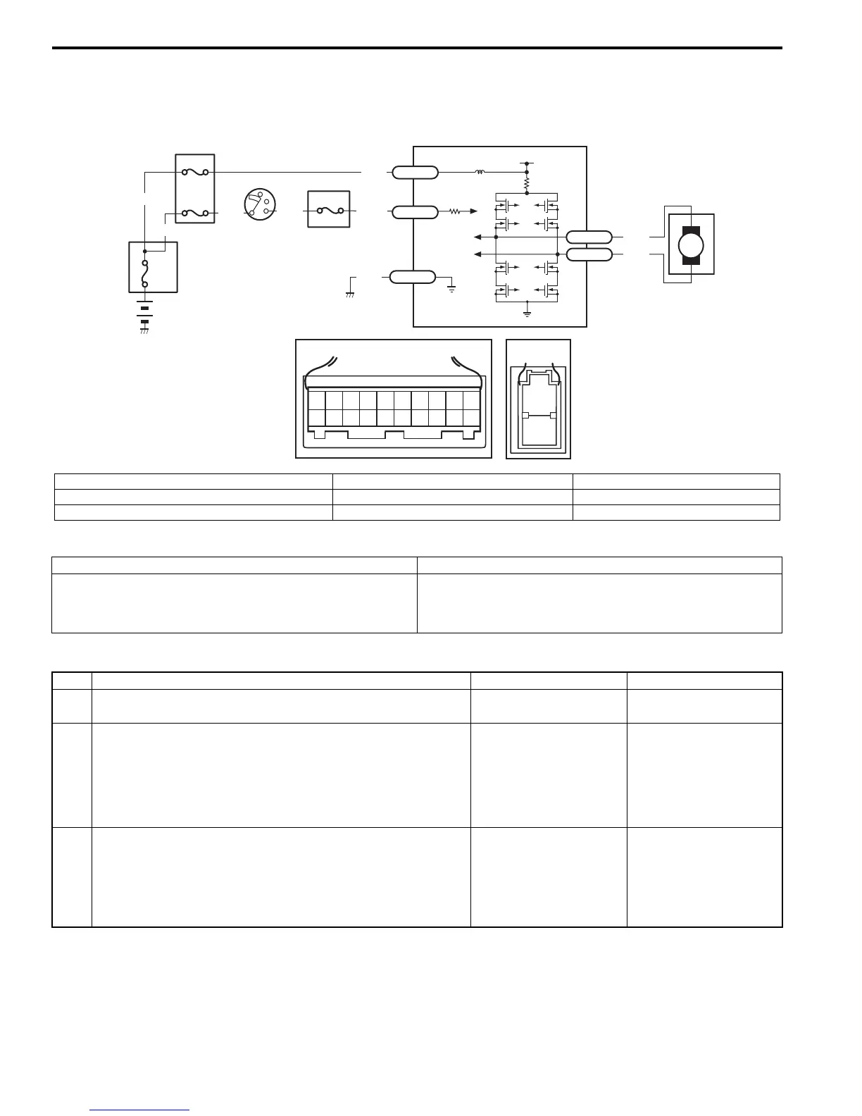
Wiring Diagram
DTC Detecting Condition and Trouble Area
DTC Troubleshooting
M
BLK
RED
E51-1
E51-2
12V
5
[A]
12
3
4
5
67
8
9
11
10
12 13
14
15
16
17 18 19
20
[B]
1
2
LT GRN
/BLK
E52-1
E49-1
GRN
GRN
WHT
BLK
WHY
6
3
4
4
4
4
1
2
E49-2
BLK
I7RS0B630011-01
[A]: Connector “E52” (viewed from harness side) 2. Ignition switch 5. P/S control module
[B]: Connector “E49” (viewed from harness side) 3. Junction block assembly 6. Individual circuit fuse box No.1
1. Main fuse box 4. Fuse
DTC detecting condition Trouble area
Power supply voltage of P/S control module is less than 9
V for 5 seconds continuously
(1 driving cycle detection logic)
• P/S control module power supply circuit
• Undercharged Battery
• P/S control module
Step Action Yes No
1 Was “EPS System Check” performed? Go to Step 2. Go to “EPS System
Check”.
2 Battery voltage check
1) Check circuit fuse for P/S control module.
2) If OK, measure voltage between positive battery terminal
and vehicle body ground with engine running.
Is voltage 10 V or more?
Go to Step 3. Check charging system
referring to “Generator
Test (Undercharged
Battery Check) in
Section 1J”.
3 P/S control module power supply circuit check
1) Check power supply circuit and ground circuit for P/S
control module referring to “P/S Control Module Power
Supply and Ground Circuit Check”.
Is check result in good condition?
Substitute a known-
good P/S control
module and recheck.
Repair defective circuit.

 Loading...


