Instrumentation / Driver Info. / Horn: 9C-4
Schematic and Routing Diagram
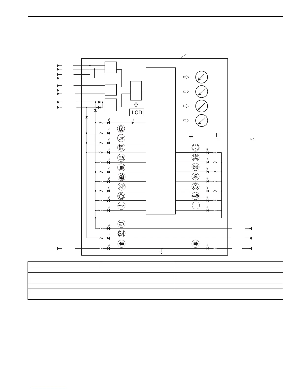
Combination Meter Circuit Diagram
S7RS0B9302001
16
15
14
13
G28-5
5
6
3
G28-267
G28-22 19
G28-25 20
G28-1 7
12
10
11
21
9
17
G28-30
4
G28-29
18
G28-16
G28-9
G28-10
G28-8
G28-7
1
2
8
G38-31
G38-32
I7RS0B930002-01
1. Keyless start control module 8. CAN driver 15. Fuel meter
2. BCM 9. Interface circuit 16. ECT meter
3. SDM 10. Power supply 17. Stepper motor and LED output driver
4. Fuel level sensor 11. CPU 18. A/T shift position indicator (“P”, “R”, “N”, “D”, “3”, “2”, and “L”)
5. RADIO fuse 12. ODO-TRIP 19. Combination switch (high beam)
6. METER fuse 13. Tachometer 20. P/S control module
7. Combination switch 14. Speedometer 21. Combination meter

 Loading...


