8B-84 Air Bag System:
DTC B1361 / B1365: Driver / Passenger Side Curtain-Air Bag Initiator Circuit Resistance High
S7RS0B8204043
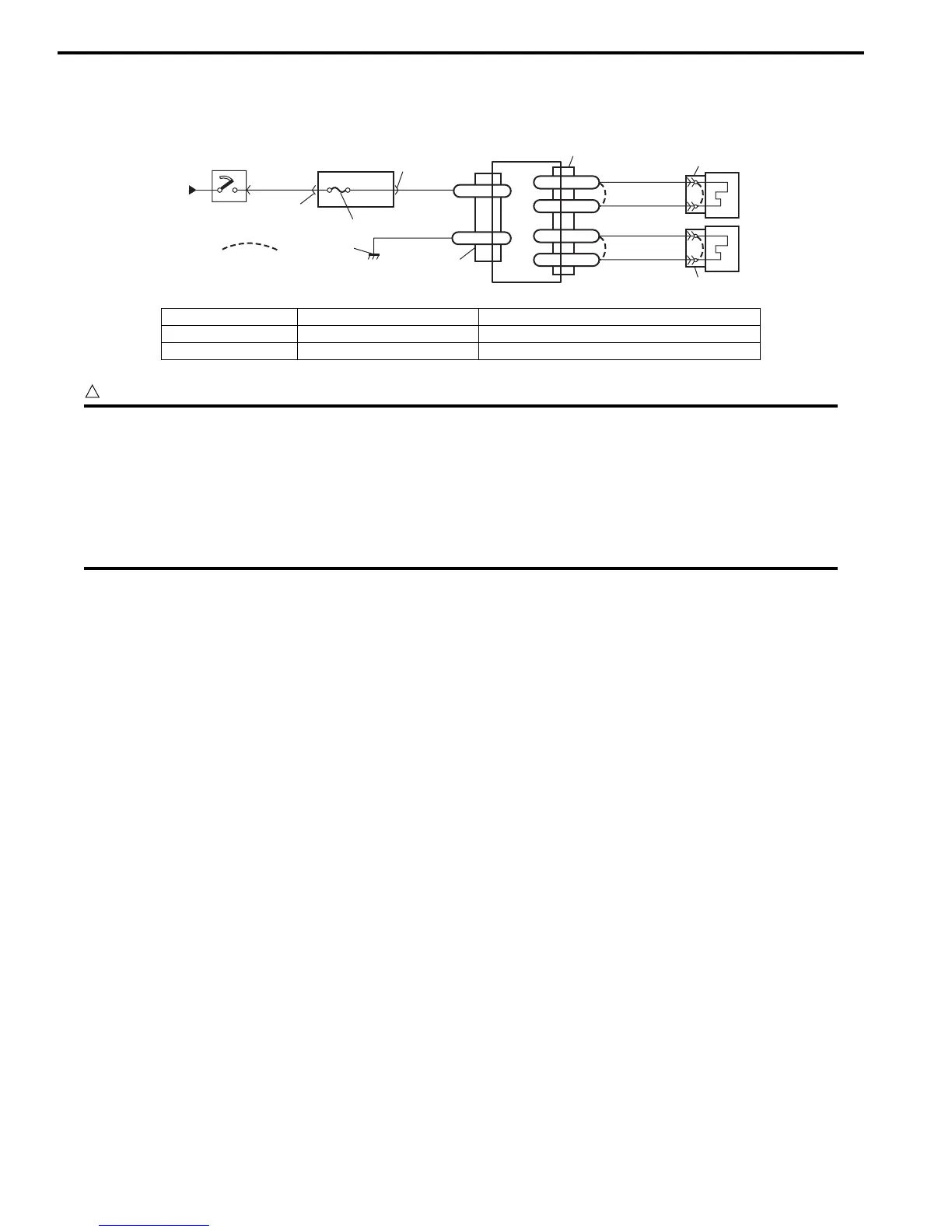
Wiring Diagram
CAUTION
!
• Be sure to perform “Air Bag Diagnostic System Check” before starting diagnosis according to flow.
• When measurement of resistance or voltage is required in this flow, use a tester along with a correct
terminal adapter from special tool (Connector test adapter kit).
• When a check for proper connection is required, refer to “Inspection of Intermittent and Poor
Connections”.
• If there is open circuit in the air bag wire harness, connector or terminal is found damaged, replace
the wire harness, connector and terminal as an assembly.
DTC Will Set when
The combined resistance of the side curtain-air bag (inflator) module (driver or passenger), harness wiring and
connector terminal contact is above a specified value for specified time.
Flow Test Description
Step 1: Check whether malfunction is in side curtain-air bag (inflator) module.
Step 2: Check side curtain-air bag initiator circuit.
1
2
3
GRN
RED
8
BLK
L29-27
L29-28
IG
E1
4
“L29”
“L04”
“G32”
“L29”
L29-20
DC+
L29-19
DC-
YEL/BLU
YEL/GRN
5
6
“L18”
L29-21
PC+
L29-22
PC-
BRN/YEL
BLK/YEL
7
“L41”
[A]
I7RS0A820031-04
[A]: Shorting bar 3. “A/BAG” fuse 6. Driver side curtain-air bag (inflator) module
1. From main fuse 4. Junction block assembly 7. Passenger side curtain-air bag (inflator) module
2. Ignition switch 5. SDM 8. Ground for air bag system

 Loading...


