1A-66 Engine General Information and Diagnosis:
DTC P0107: Manifold Absolute Pressure / Barometric Pressure Circuit Low Input
S7RS0B1104021
Wiring Diagram
Refer to “DTC P0106: Manifold Absolute Pressure / Barometric Pressure Circuit Range / Performance”
DTC Detecting Condition and Trouble Area
DTC Confirmation Procedure
1) Connect scan tool to DLC with ignition switch turned OFF.
2) Turn ON ignition switch and clear DTC using scan tool.
3) Run engine at idle speed for 1 min.
4) Check DTC.
DTC Troubleshooting
NOTE
• When measuring circuit voltage, resistance and/or pulse signal at ECM connector, connect the
special tool to ECM and/or the ECM connectors referring to “Inspection of ECM and Its Circuits”.
• Upon completion of inspection and repair work, perform “DTC Confirmation Procedure” and
confirm that the trouble has been corrected.
DTC detecting condition Trouble area
Manifold absolute pressure sensor output voltage is lower
than specified value for specified time continuously.
(1 driving cycle detection logic)
• Manifold absolute pressure sensor circuit
• Manifold absolute pressure sensor
• A/C refrigerant pressure sensor (if equipped with A/C)
•ECM
Step Action Yes No
1 Was “Engine and Emission Control System Check”
performed?
Go to Step 2. Go to “Engine and
Emission Control
System Check”.
2 MAP sensor and its circuit check
1) Connect scan tool to DLC with ignition switch turned
OFF.
2) Turn ON ignition switch.
3) Check intake manifold pressure displayed on scan tool.
Is it 0 kPa (0 in.Hg)?
Go to Step 3. Intermittent trouble.
Check for intermittent
referring to “Intermittent
and Poor Connection
Inspection in Section
00”.
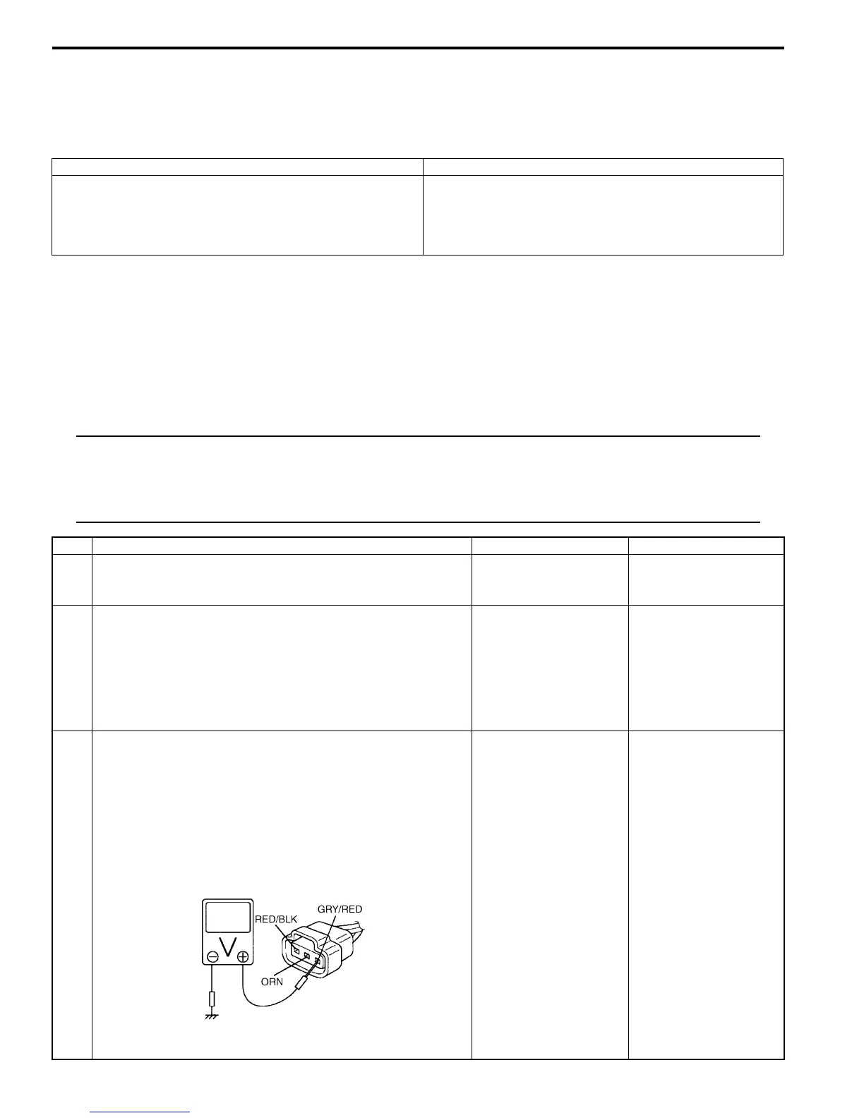
3 MAP sensor power supply voltage check
1) Disconnect connector from MAP sensor with ignition
switch turned OFF.
2) Check for proper connection of MAP sensor at “GRY/
RED”, “RED/BLK” and “ORN” wire terminals.
3) Turn ON ignition switch, measure voltage between
engine ground and “GRY/RED” wire terminal of MAP
sensor connector.
Is voltage 4 – 6 V?
Go to Step 5. Go to Step 4.
I4RS0B110019-03

 Loading...


