4F-26 Electronic Stability Program:
Serial Data Link Circuit Check
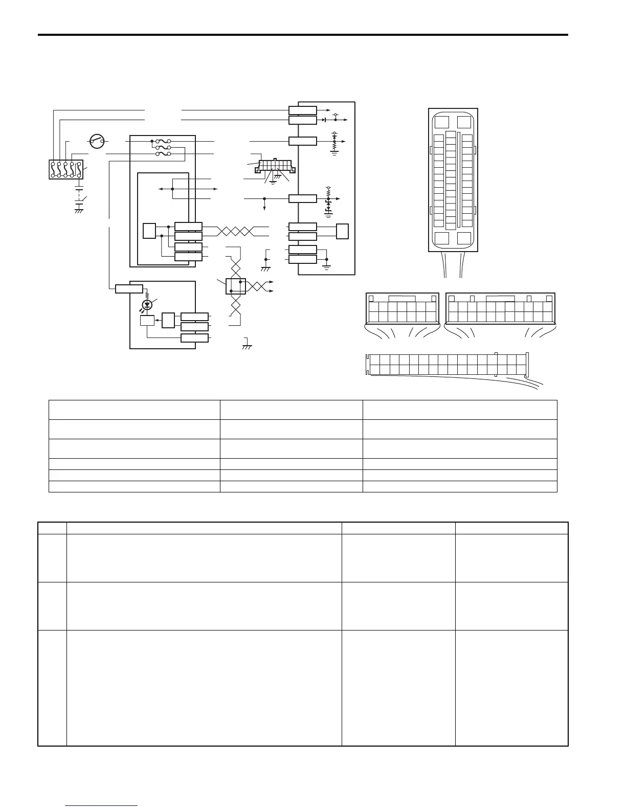
S7RS0B4604012
Wiring Diagram
Inspection
[A]
E85
16
1
15
2
3
4
5
6
7
8
9
10
11
12
13
14
17
18
19
20
21
22
23
24
25
26
27
28
29
30
31
32
33
34
35
36
37
38
39
40
41
42
43
44
45
46
47
WHT
GRN
3
E85-13
RED
WHT
6
5
E46-1
E46-2
4
10
6
E85-16
E85-47
BLK
BLK
8
9
BLK/ORN
RED
WHT
RED
WHT
G37-4
G37-2
G28-10
G28-8
G28-16
G28-31
12V
12V
E85-32
E85-1
E85-35
WHT/RED
WHT/BLU
GRN/ORN
6
2
1
7
14
15
[B]
G37E46
1245367
891011121314
1245367
891011
1213141516171819202122
[C]
G28
12345678910111213141516
17181920212223242526272829303132
12V
11
PPL/WHT
PPL/WHT
E85-33
E85-44
12
13
WHT
WHT/RED
B
G
G1
RED/BLK
I6RS0B460012-01
[A]: ESP® control module connector (viewed
from terminal side)
4. Junction block assembly 10. ESP® hydraulic unit / control module assembly
[B]: BCM connector (viewed from harness side) 5. BCM (included in junction block
assembly)
11. Data link connector (DLC)
[C]: Combination meter connector (viewed from
harness side)
6. CAN driver 12. To SDM
1. Battery 7. Combination meter 13. To ECM and P/S control module
2. Main fuse box 8. ESP® warning lamp 14. Junction connector
3. Ignition switch 9. Lamp driver module 15. To steering angle sensor
Step Action Yes No
1 Check ESP® warning lamp
1) Turn ignition switch to ON position.
Does ESP
®
warning lamp come ON?
Go to Step 2. Go to Step 6.
2 Check fuse
1) Turn ignition switch to OFF position.
Are main fuses for good condition?
Go to Step 3. Replace fuse and check
for short.
3 Check ESP® control module power supply circuit
1) Disconnect ESP® control module connector.
2) Check for proper connection to ESP® control module
connector at terminal “E85-35”.
3) If OK, then turn ignition switch to ON position and
measure voltage between terminal “E85-35” and vehicle
body ground.
Is it 10 – 14 V?
Go to Step 4. “GRN/ORN” wire circuit
open.

 Loading...


