Clutch: 5C-5
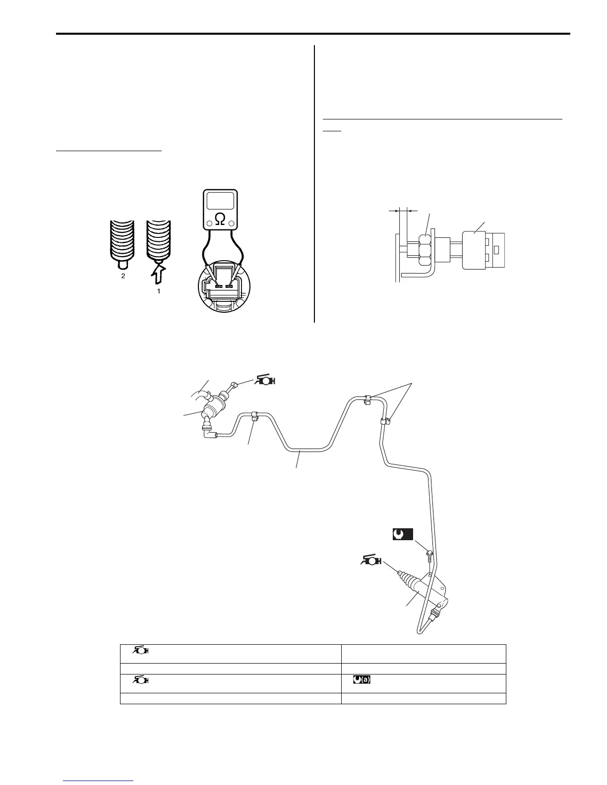
Clutch Pedal Position (CPP) Switch Inspection
and Adjustment
S7RS0B5306005
Inspection
Check for resistance between terminals under each
condition below. If check result is not satisfactory,
replace.
CPP switch resistance
When switch shaft is pushed (1): Continuity
When switch shaft is free (2): No continuity
Adjustment
With clutch pedal depressed, adjust switch (1) position
so that clearance between end of thread and clutch
pedal arm is within specification, and then tighten lock
nut to specified torque.
Clearance between end of thread and clutch pedal
arm
“a”: 3.5 – 4.0 mm (0.14 – 0.16 in.)
Tightening torque
CPP switch lock nut (a): 7.5 N·m (0.75 kgf-m, 5.5 lb-
ft)
Clutch Fluid Pipe and Hose Components
S7RS0B5306006
I5JB0A530006-01
(a)
1
“a”
I6RS0C530002-01
6
1
5
2
5
4
(a)
3
I6RS0C530003-01
1. Master cylinder
: Apply grease 99000-25100 to push rod end.
5. Clamp
2. Pipe 6. Clutch reservoir hose
3. Operating cylinder
: Apply grease 99000-25100 to rod tip.
: 23 N⋅m (2.3 kgf-m, 17.0 lb-ft)
4. Operating cylinder bolt

 Loading...


