Engine General Information and Diagnosis: 1A-143
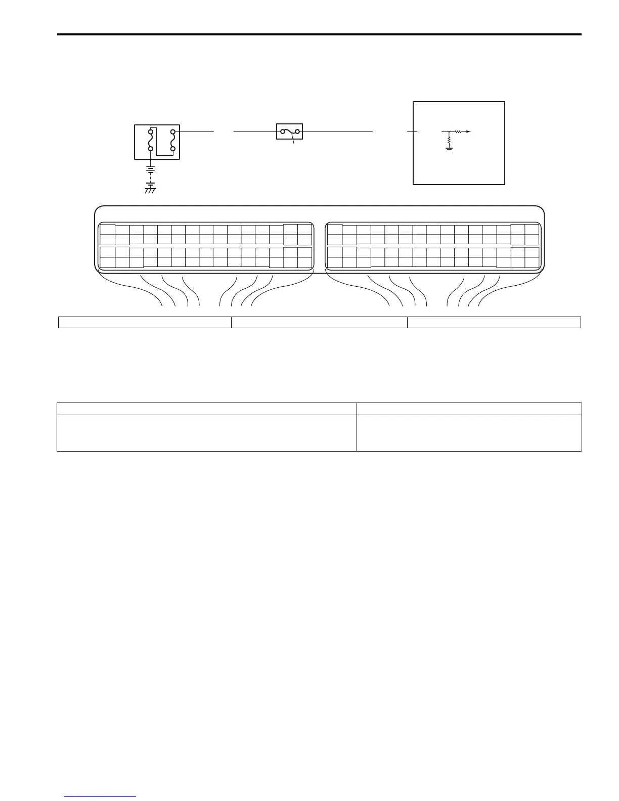
DTC P1510: ECM Back-Up Power Supply Malfunction
S7RS0B1104060
Wiring Diagram
Circuit Description
Battery voltage is supplied so that DTC memory, values for engine control learned by ECM, etc. are kept in ECM even
when the ignition switch is turned OFF.
DTC Detecting Condition and Trouble Area
DTC Confirmation Procedure
1) Connect scan tool to DLC with ignition switch turned OFF.
2) Turn ON ignition switch and clear DTC using scan tool and run engine at idle speed for 1 min.
3) Check DTC.
E23 C37
34
1819
5671011
1720
47 46495051
2122
52
1625
9
24
14
29
5557 54 53
59
60 58
2
262728
15
30
56 48
32 31343536374042 39 38
44
45 43 41 33
11213
23
834
1819
5671011
1720
47 46495051
2122
52
1625
9
24
14
29
5557 54 53
59
60 58
2
262728
15
30
56 48
32 31343536374042 39 38
44
45 43 41 33
11213
23
8
WHT/REDWHT
80A
50A
3
2
1
E23-2
I4RS0A110051-01
1. ECM 2. “RADIO” fuse 3. Main fuse box
DTC detecting condition Trouble area
Back-up power circuit voltage is less than 70% battery voltage for
5 seconds continuously while engine is running.
(1 driving cycle detection logic)
Battery voltage supply circuit

 Loading...


