Engine General Information and Diagnosis: 1A-109
DTC P0335: Crankshaft Position (CKP) Sensor “A” Circuit
S7RS0B1104041
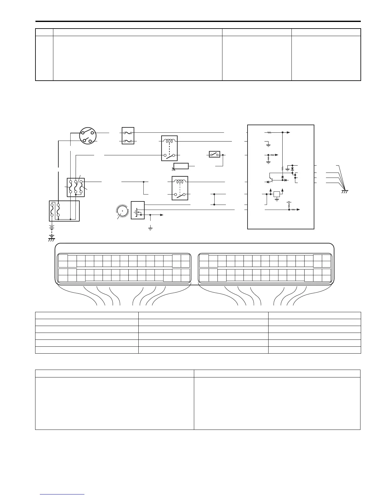
Wiring Diagram
DTC Detecting Condition and Trouble Area
DTC Confirmation Procedure
1) With ignition switch turned OFF, connect scan tool.
2) Turn ON ignition switch and clear DTC using scan tool.
3) Crank engine for 3 – 5 sec.
4) Check DTC.
7 Knock sensor circuit for high resistance check
1) Turn OFF ignition switch, measure resistance between
“C37-56” terminal of ECM connector and “RED” wire
terminal of knock sensor harness connector.
Is resistance below 5
Ω
?
Faulty knock sensor. “RED” wire is high
resistance circuit.
Step Action Yes No
E23 C37
34
1819
5671011
1720
47 46495051
2122
52
1625
9
24
14
29
5557 54 53
59
60 58
2
262728
15
30
56 48
32 31343536374042 39 38
44
45 43 41 33
11213
23
834
1819
5671011
1720
47 46495051
2122
52
1625
9
24
14
29
5557 54 53
59
60 58
2
262728
15
30
56 48
32 31343536374042 39 38
44
45 43 41 33
11213
23
8
12V
5V
BLK/RED
BLK/RED
BLK/YEL
BLK/YEL
BLK/YEL
BRN/WHT
5
9
4
13
3
C37-30
C37-15
C37-58
E23-31
BLK/ORN
BLK
BLK
BLK
10
BLK/RED
BLK/RED
E23-16
E23-60
E23-1
BLK/ORN
1
15
C37-21
5V
7
RED/WHT
GRN/WHT
GRN
RED
BLK/WHT
YEL/GRN
YEL/GRN
WHT
[A]: YEL
[B]: YEL/GRN
6
8
12
11
14
PNK
2
WHT
WHT/BLU
C37-48
E23-30
E23-29
I6RS0C110016-01
[A]: For A/T model 5. Ignition switch 11. “ST MOT” fuse
[B]: For M/T model 6. Starting motor 12. “ST SIG” fuse
1. CKP sensor 7. Starting motor control relay 13. “IG COIL” fuse
2. Sensor plate on crankshaft 8. Transmission range switch (for A/T model) 14. “IG ACC” fuse
3. ECM 9. Main fuse box 15. To CMP sensor
4. Main relay 10. “FI” fuse
DTC detecting condition Trouble area
No CKP sensor signal for 2 sec. even if starting motor
signal is inputted at engine cranking.
(1 driving cycle detection logic)
• CKP sensor circuit open or short
• Sensor plate teeth damaged
• CKP sensor malfunction, foreign material being attached
or improper installation
•ECM
• Engine start signal circuit malfunction

 Loading...


