1A-124 Engine General Information and Diagnosis:
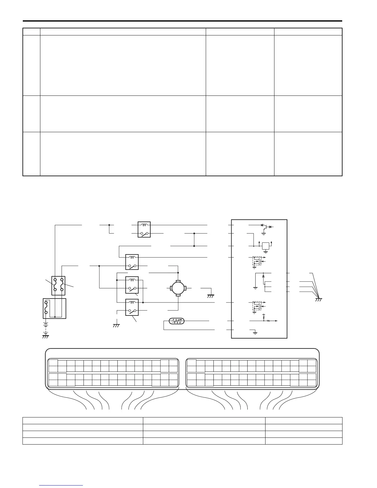
DTC P0480: Fan 1 (Radiator Cooling Fan) Control Circuit
S7RS0B1104050
Wiring Diagram
5 Wire circuit check
1) Connect connector to purge control valve with ignition
switch turned OFF.
2) Turn ON ignition switch and measure voltage between
“C37-29” terminal of ECM connector and vehicle body
ground.
Is it voltage 10 – 14 V?
Go to Step 6. “BLU/BLK” wire is open
circuit.
6 EVAP canister purge control valve check
1) Check EVAP canister purge control valve referring to
“EVAP Canister Purge Valve Inspection in Section 1B”.
Is it in good condition?
Go to Step 7. Faulty EVAP canister
purge control valve.
7 EVAP canister purge control circuit check
1) With ignition switch turn OFF, measure resistance
between “E23-1/16” terminal and “C37-29” terminal of
ECM connector.
Is resistance below 40
Ω
at 20
°
C, 68
°
F?
Faulty ECM. Substitute
a known-good ECM and
recheck.
“BLK/RED” and/or
“BLU/BLK” wire are high
resistance circuit.
Step Action Yes No
E23 C37
34
1819
5671011
1720
47 46495051
2122
52
1625
9
24
14
29
5557 54 53
59
60 58
2
262728
15
30
56 48
32 31343536374042 39 38
44
45 43 41 33
11213
23
834
1819
5671011
1720
47 46495051
2122
52
1625
9
24
14
29
5557 54 53
59
60 58
2
262728
15
30
56 48
32 31343536374042 39 38
44
45 43 41 33
11213
23
8
BLK/REDBLK/RED
BLK/YEL BLK/YEL
BLK/YEL
BRN/WHT
12V
5V
5V
2
8
E23-1
E23-60
C37-58
C37-15
C37-30
BLK/ORN
BLK
BLK
E23-31
BLK
BLK/RED
LT GRN
BLK/RED
E23-16
E23-46
L+
L–
H–
H
+
BLU/RED
BLK
BLUWHT
BLK
BLU/BLK
BLU/RED
4
GRN
GRY
E23-48
LT GRN
ORN
C37-24
C37-55
3
5
6
7
10
9
1
I6RS0C110022-02
1. Individual circuit fuse box No.1 5. Radiator cooling fan relay No. 3 9. “FI” fuse
2. Main relay 6. Radiator cooling fan motor 10. “RDTR FAN” fuse
3. Radiator cooling fan relay No. 1 7. ECT sensor
4. Radiator cooling fan relay No. 2 8. ECM

 Loading...


