Electronic Stability Program: 4F-37
DTC C1037: Steering Angle Sensor Power Supply Failure
S7RS0B4604033
Wiring Diagram
DTC Detecting Condition and Trouble Area
4 Check yaw rate / G sensor assembly power supply
circuit
1) Turn ignition switch to OFF position.
2) Disconnect ESP® control module connector.
3) Check for proper connection to ESP® control module
connector terminals at “E85-31” and “E85-37”.
4) If OK, then measure voltage between connector terminal
“E85-37” and vehicle body ground.
Is it 0 V?
Go to Step 5. “BLU/RED” wire circuit
is shorted to power
circuit.
5 Check yaw rate / G sensor assembly power supply
circuit
1) Measure resistance between the following points.
• Between terminal “E85-37” of module connector and
terminal “E84-3” of sensor terminal.
• Between terminal “E85-31” of module connector and
terminal “E84-5” of sensor terminal.
Are resistance less than 2
Ω
?
Substitute a known-
good ESP® hydraulic
unit / control module
assembly recheck.
“BLU/RED” and/or
“GRN/BLK” wire circuit
open or high resistance.
Step Action Yes No
[A]
E85
16
1
15
2
3
4
5
6
7
8
9
10
11
12
13
14
17
18
19
20
21
22
23
24
25
26
27
28
29
30
31
32
33
34
35
36
37
38
39
40
41
42
43
44
45
46
47
[C]
G37E46
1245367
891011121314
1245367
891011
1213141516171819202122
WHT
GRN
3
E85-13
E85-44
RED
WHT
6
5
E46-1
E46-2
4 8
6
BLK/ORN
RED
WHT
RED
WHT
G37-4
G37-2
G50-10
G50-9
G50-2
6
2
1
7
9
10
G50-1
G50-3
GRN/ORN
WHT/RED
WHT
[B]
G50
109 321
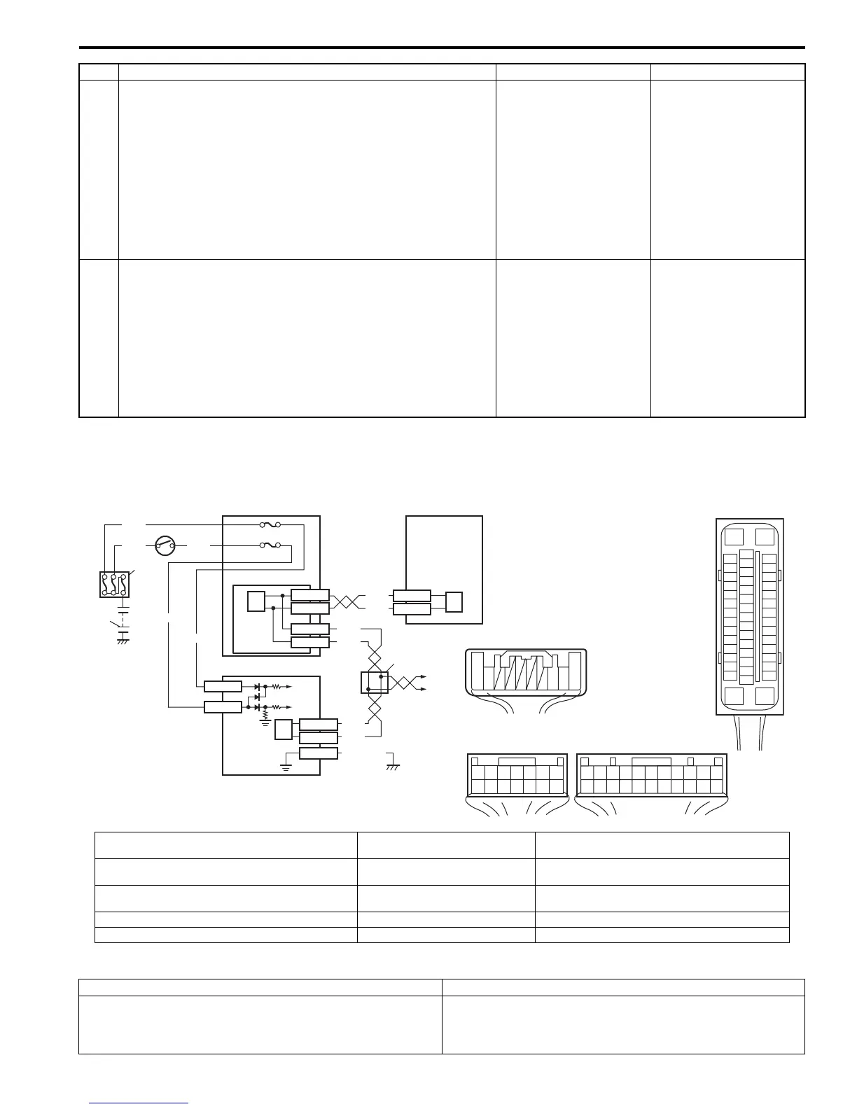
I6RS0B460020-01
[A]: ESP® control module connector (viewed from
terminal side)
3. Ignition switch 8. ESP® hydraulic unit control module assembly
[B]: Steering angle sensor connector (viewed from
harness side)
4. Junction block assembly 9. Junction connector
[C]: BCM connector (viewed from harness side) 5. BCM (included in junction block
assembly)
10. To Combination meter and keyless start control
module
1. Battery 6. CAN driver
2. Main fuse box 7. Steering angle sensor
DTC Detecting Condition Trouble Area
Power supply voltage to steering angle sensor is too low. • Steering angle sensor power supply circuit
• Steering angle sensor
• ESP® control module

 Loading...


