5B-12 Manual Transmission/Transaxle:
4) Install washer and gear shift interlock bolt (2) to
which sealant have been applied and then tighten it
to specified torque.
“B”: Sealant 99000–31260 (SUZUKI Bond
No.1217G)
Tightening torque
Gear shift interlock bolt (b): 23 N·m (2.3 kgf-m,
17.0 lb-ft)
5) Install washer and 5th to reverse interlock guide bolt
(3) to which sealant have been applied and then
tighten it to specified torque.
“B”: Sealant 99000–31260 (SUZUKI Bond
No.1217G)
Tightening torque
5th to reverse interlock guide bolt (c): 23 N·m (
2.3 kgf-m, 17.0 lb-ft)
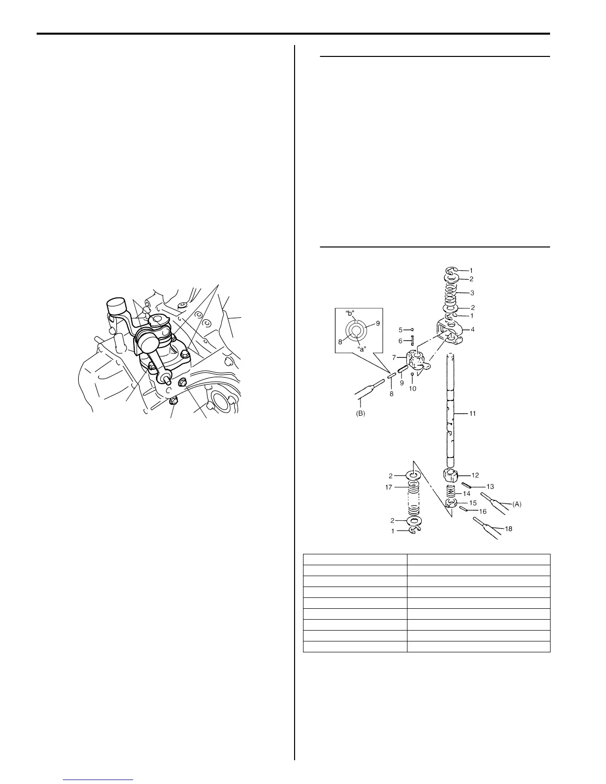
Gear Shift and Select Shaft Disassembly and
Assembly
S7RS0B5206012
1) Push pins out using 2.8 – 3.0 mm (0.11 – 0.12 in.)
commercially available spring pin remover and
specified spring pin removers as shown below.
Special tool
(A): 09922–85811 4.5 mm
(B): 09925–78210 6.0 mm
2) Inspect component parts for wear, distortion or
damage. If any detect is found, replace detective
part with new one.
NOTE
• Set new gear shift & select lever inner pin
(8) and outer pin (9) facing each gap (“a”,
“b”) in the opposite direction as shown in
figure.
• When driving in pins, prevent shaft from
being bent by supporting it with wood
block.
• Assemble 5th & reverse gear shift cam
with its pit and pin aligned.
• Make sure to select an appropriate spring
by identifying the painted colors to keep
gear shifting performance as designed.
– Low speed select spring – Light blue
– Reverse select spring – Yellow
“A”
1, (a), “B”
1, (a), “B”
2, (b), “B”3, (c), “B”
I4RS0A520025-01
1. E-ring 10. Ball
2. Washer 11. Gear shift & select shaft
3. Reverse select spring 12. 5th & reverse gear shift cam
4. Gear shift interlock plate 13. 5th & reverse gear shift cam guide pin
5. Ball 14. Cam guide return spring
6. Gear shift interlock spring 15. 5th & reverse gear shift cam guide
7. Gear shift & select lever 16. Gear shift cam guide pin
8. Inner pin 17. Low speed select spring
9. Outer pin 18. Spring pin remover
I6RS0C520011-01

 Loading...


