10B-31 Body Electrical Control System:
Inspection of BCM and its Circuits
S7RS0BA204018
BCM and its circuits can be checked at BCM wiring couplers by measuring voltage and resistance.
CAUTION
!
BCM cannot be checked by itself. It is strictly prohibited to connect voltmeter or ohmmeter to BCM
with couplers disconnected from it.
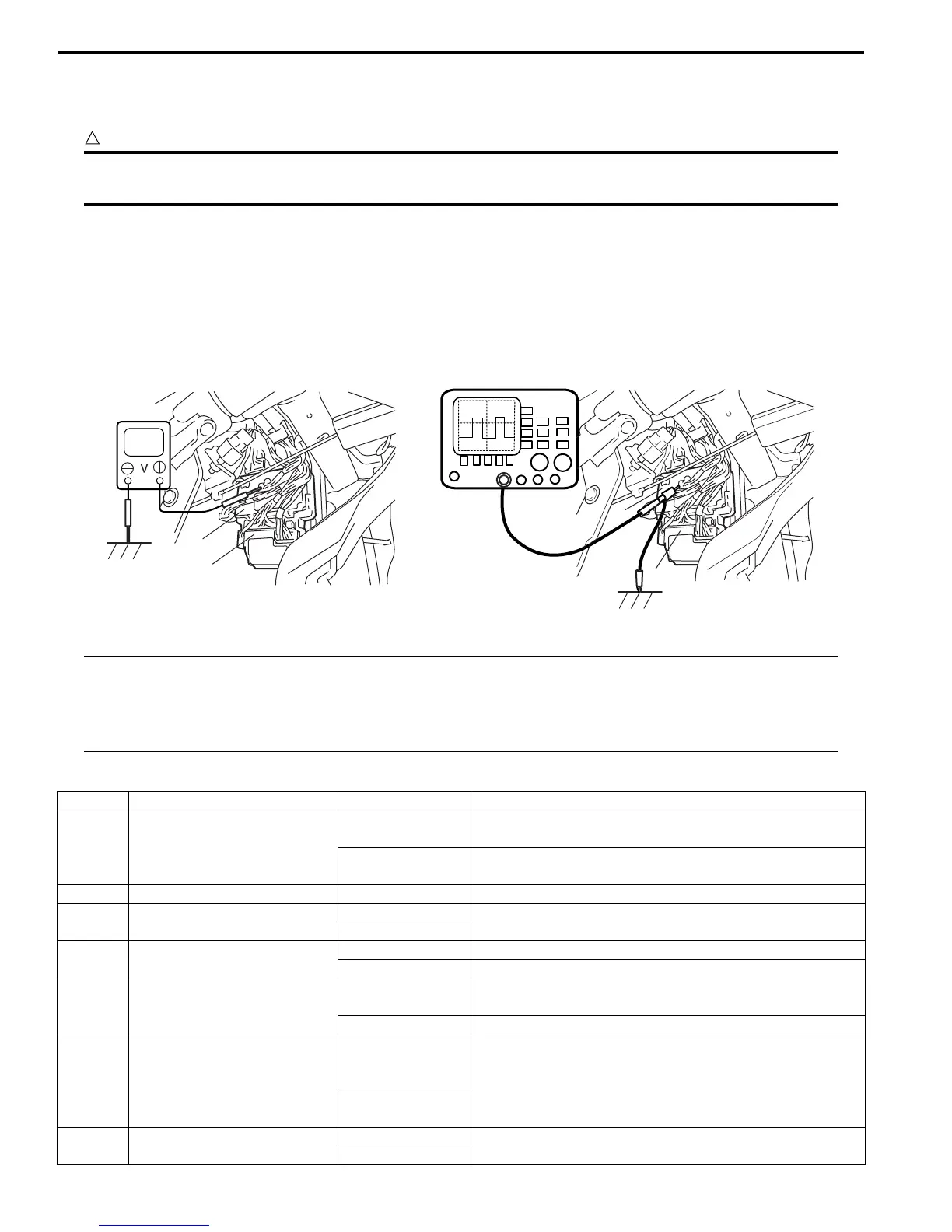
Voltage Check
1) Disconnect negative (–) cable at battery.
2) Remove BCM (included in junction block assembly) referring to “BCM (Included in Junction Block Assembly)
Removal and Installation”.
3) Connect connectors to BCM (1) and junction block assembly (2).
4) Check voltage at each terminal number of couplers connected.
For connector and terminal number, refer to “Connector Layout Diagram of BCM and Junction Block Assembly”.
NOTE
• As each terminal voltage is affected by the battery voltage, confirm that it is 11 V or more when
ignition switch is ON.
• Voltage with asterisk (*) can not be measured by voltmeter because it is pulse signal.
Check it with oscilloscope if necessary.
BCM connector “L01”
1
2
1
2
I4RS0AA20030-01
Terminal Circuit Normal voltage Condition
L01-1
Passenger side door lock
actuator control
(Unlock) (if equipped)
10 – 14 V
Unlock signal is output for passenger side door lock
actuator
0 V
Unlock signal is not output for passenger side door lock
actuator
L01-2 — — —
L01-3 Rear end door switch
10 – 14 V Rear end door is closed
0 V Rear end door is opened
L01-4 Rear end door opener switch
10 – 14 V Rear end door switch is not pushed
0 V Rear end door switch is pushed
L01-5
Manual door lock switch
(Unlock)
10 – 14 V
Manual door lock switch is at any position other than
unlock position
0 V Manual door lock switch is at unlock position
L01-6 Parking brake switch
*0 – 3 V
↑↓
10 – 14 V
Refer to “Reference waveform No. 1: ”
0 V
Ignition switch is at ON position and parking brake lever
is pulled up
L01-7 Driver side door switch
10 – 14 V Driver side door is closed
0 V Driver side door is opened

 Loading...


