4F-22 Electronic Stability Program:
Troubleshooting
ESP® Warning Lamp Comes ON Steady
S7RS0B4604009
Wiring Diagram
Refer to “Wiring Diagram” under “ESP® Warning Lamp Does Not Come ON at Ignition Switch ON”.
Circuit Description
Refer to “Circuit Description” under “ESP® Warning Lamp Does Not Come ON at Ignition Switch ON”.
Troubleshooting
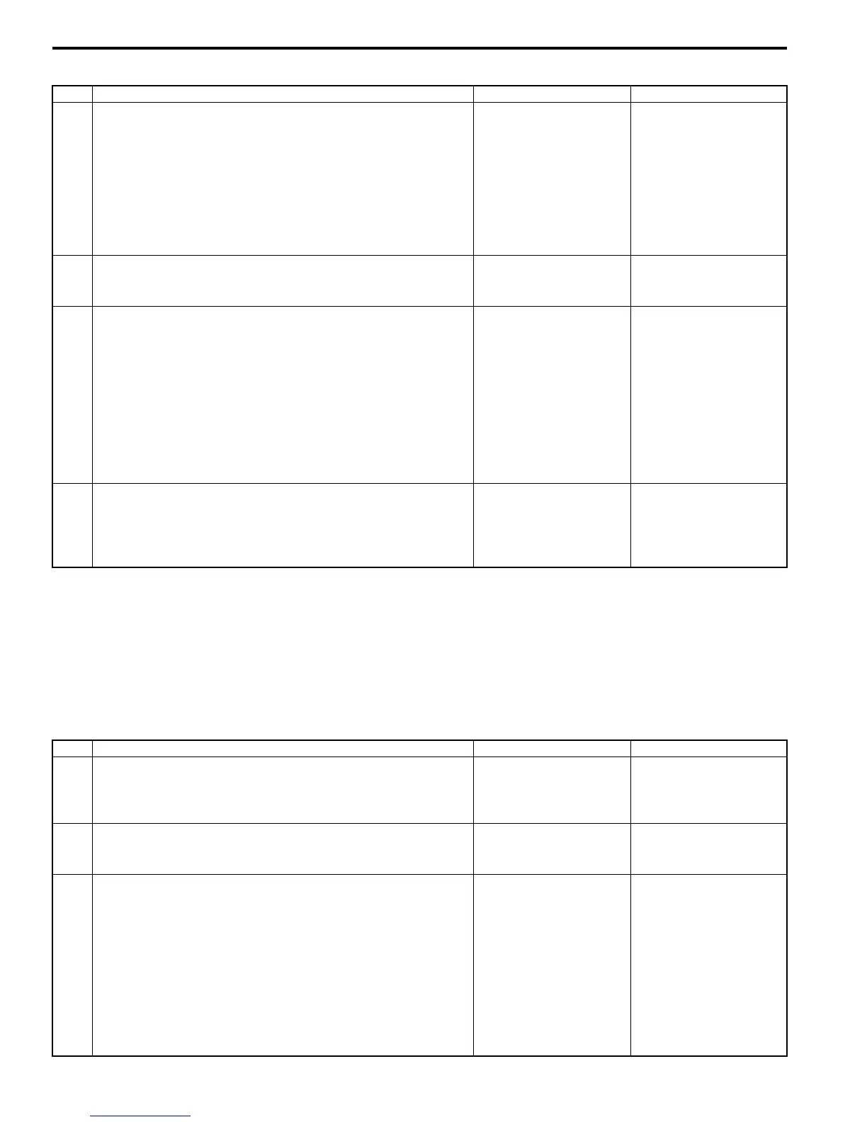
Step Action Yes No
1 Check warning lamp
1) Turn ignition switch to ON position.
Do other warning lamps come ON?
Substitute a known-
good combination meter
and recheck. If ESP®
warning lamp remains
OFF, substitute a
known-good ESP®
hydraulic unit / control
module assembly and
recheck.
Go to Step 2.
2 Check fuse
Is Circuit fuse for combination meter in good condition?
Go to Step 3. Replace fuse and check
for short circuit to
ground.
3 Check combination meter power supply circuit
1) Remove combination meter with ignition switch turned
OFF.
2) Check for proper connection to combination meter
connector terminal at “G28-31” and “G28-16”.
3) If OK, turn ON ignition switch and measure voltage
between connector terminal “G28-31” and vehicle body
ground.
Is it 10 – 14 V?
Go to Step 4. Repair power supply
circuit for combination
meter.
4 Check combination meter ground circuit
1) Measure resistance between connector terminal “G28-
16” and vehicle body ground.
Is resistance less than 2
Ω
?
Replace combination
meter.
“BLK/ORN” circuit open
or high resistance.
Step Action Yes No
1 DTC Check for ESP®
1) Perform diagnostic trouble code check.
Is there any DTC(s)?
Go to applicable DTC
diag. flow.
Go to Step 2.
2 Check fuse
Are main fuses for good condition?
Go to Step 3. Replace fuse and check
circuit for short to
ground.
3 Check ESP® control module power supply circuit
1) Turn ignition switch to OFF.
2) Disconnect ESP® control module connector.
3) Check for proper connection to ESP® control module
connector at terminals “E85-35”, “E85-16” and “E85-47”.
4) If OK, then turn ignition switch to ON position and
measure voltage between terminal “E85-35” and vehicle
body ground.
Is it 10 – 14 V?
Go to Step 4. “GRN/ORN” circuit
open.

 Loading...


