4F-30 Electronic Stability Program:
DTC Troubleshooting
DTC C1018: Brake Fluid Level Switch Failure
S7RS0B4604027
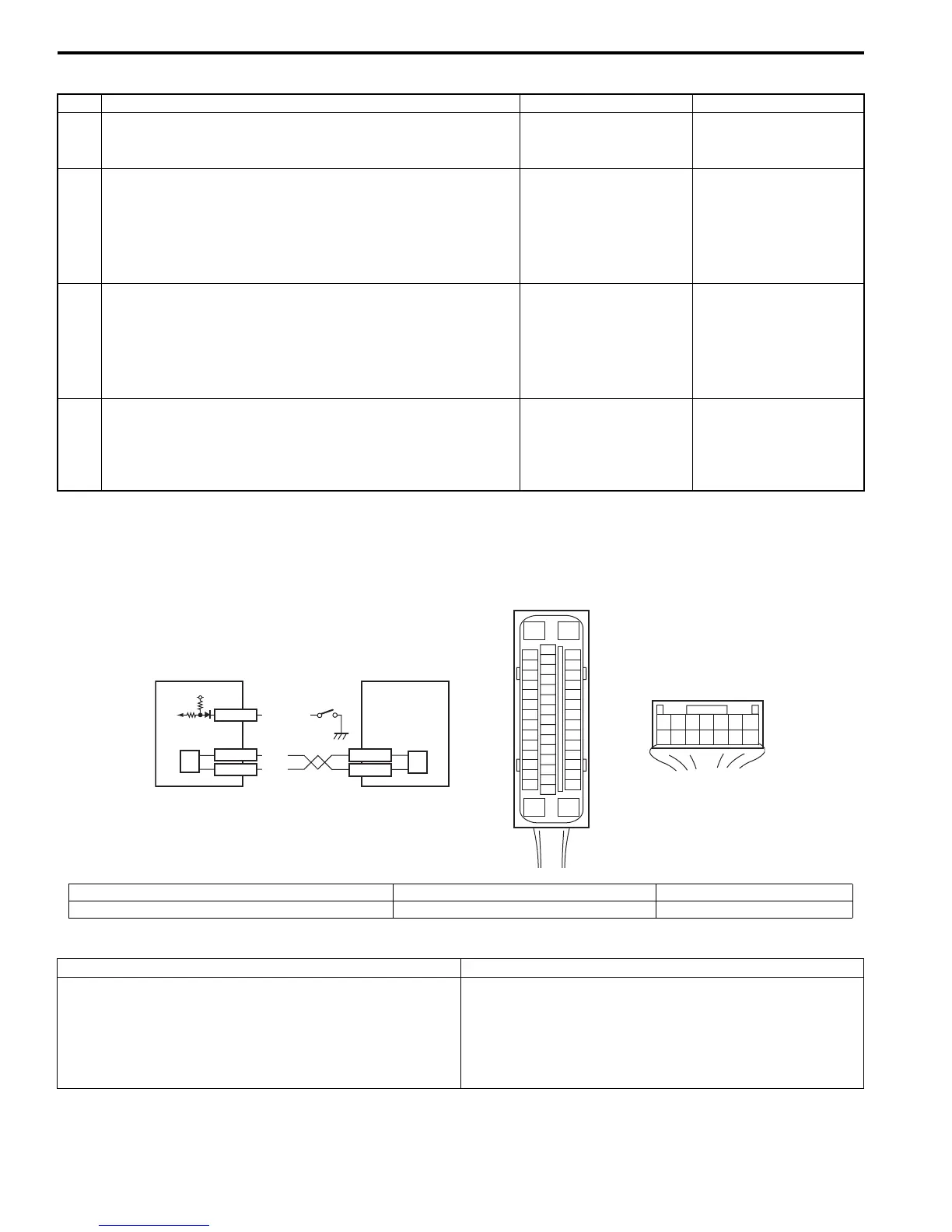
Wiring Diagram
DTC Detecting Condition and Trouble Area
Step Action Yes No
1 Was “Electronic Stability Program Check” performed? Go to Step 2. Go to “Electronic
Stability Program
System Check”.
2 DTC check for ESP®
1) Connect scan tool to DLC with ignition switch turned
OFF.
2) Turn ignition switch ON and check DTC for ESP®.
Are DTC C1034 and/or C1073 detected?
Go to applicable DTC
diag. flow.
Go to Step 3.
3 Check sensor calibration
1) Calibrate yaw rate / G sensor assembly referring to
“Sensor Calibration”.
2) Clear all DTCs and check DTC for ESP®.
Are DTC C1017 and/or C1023 still detected?
Go to Step 4. Yaw rate / G sensor
assembly calibration is
incompleted.
4 Check yaw rate / G sensor assembly
1) Check yaw rate / G sensor assembly referring to “Yaw
Rate / G Sensor Assembly On-Vehicle Inspection”.
Is it good condition?
Substitute a known-
good ESP® hydraulic
unit / control module
assembly and recheck.
Substitute a known-
good yaw rate / G
sensor assembly and
recheck.
[A]
E85
16
1
15
2
3
4
5
6
7
8
9
10
11
12
13
14
17
18
19
20
21
22
23
24
25
26
27
28
29
30
31
32
33
34
35
36
37
38
39
40
41
42
43
44
45
46
47
[B]
E46
1245367
891011121314
E85-13
E85-44
RED
WHT
4
E46-1
E46-2
12
4
12V
3
E46-5
RED/BLK
I6RS0B460015-01
[A]: ESP® control module connector (viewed from terminal side) 1. BCM 3. Brake fluid level switch
[B]: BCM connector (viewed from harness side) 2. ESP® hydraulic unit control module assembly 4. CAN driver
DTC Detecting Condition Trouble Area
• Brake fluid level is too low.
• Input signal of brake fluid level switch to BCM is low
level.
• Brake fluid level
• Brake fluid level switch circuit
• Brake fluid level switch
•BCM
• ESP® control module

 Loading...


