5A-150 Automatic Transmission/Transaxle:
Automatic Transaxle Unit Assembly
S7RS0B5106060
CAUTION
!
• Automatic transaxle consists of highly
precise parts. As even flaw in small part
may cause oil leakage or decrease in
function, check each part carefully before
installation.
• Clean all parts with compressed air. Never
use wiping cloths or rags.
• Before assembling new clutch or brake
discs, soak them in automatic transaxle
fluid for at least 2 hours.
• Be sure to use new gaskets and O-rings.
• Lubricate O-rings with automatic transaxle
fluid.
• Apply automatic transaxle fluid on sliding
or rotating surfaces of the parts before
assembly.
• Use Suzuki Super Grease “C” to retain
parts in place.
• Be sure to install thrust bearings and races
in correct direction and position.
• Make sure that snap ring ends are not
aligned with one of cut outs and are
installed in groove correctly.
• Do not use adhesive cements on gaskets
and similar parts.
• Be sure to torque each bolt and nut to
specification.
1) Install new manual shift shaft oil seal to transaxle
case.
Use special tool and hammer to install it, and then
apply grease to its lip.
Special tool
(A): 09925–98210
“A”: Grease 99000–25030 (SUZUKI Super
Grease C)
Manual shift shaft oil seal installing depth
“a”: 0.5 – 1.5 mm (0.02 – 0.06 in.)
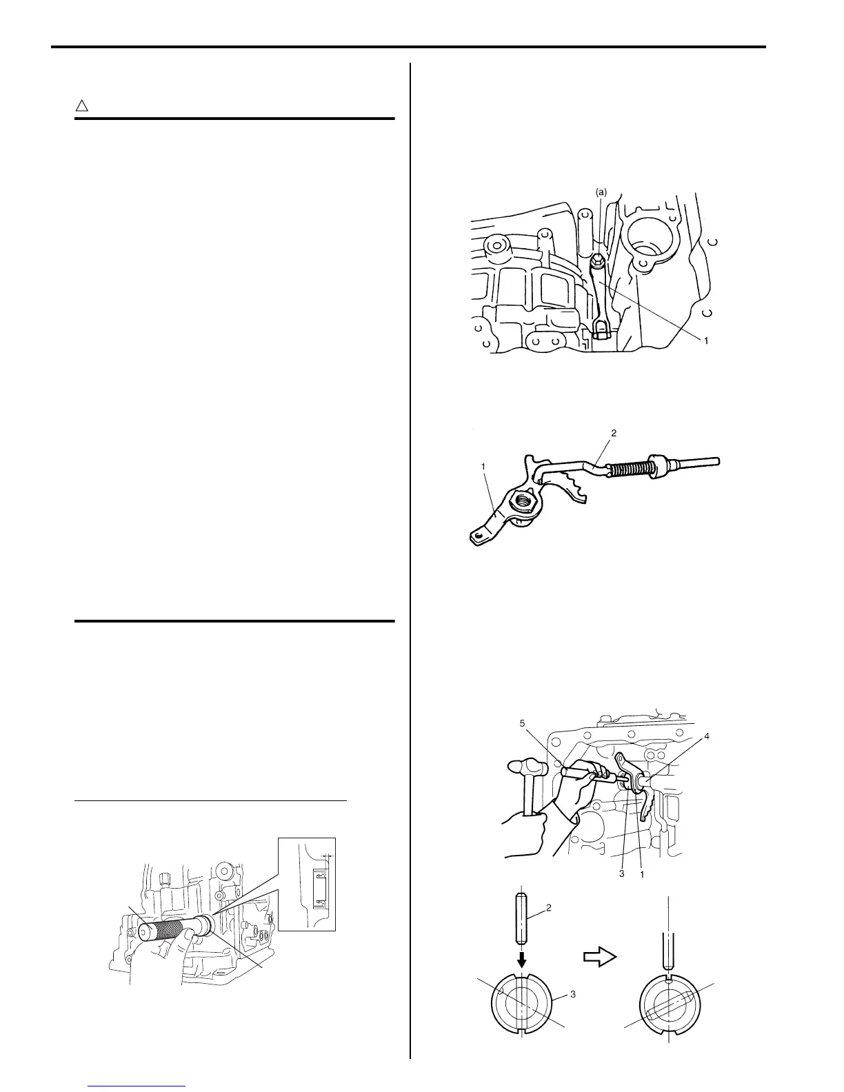
2) Install manual detent spring (1) to transaxle case
and tighten manual detent spring bolt to specified
torque.
Tightening torque
Manual detent spring bolt (a): 10 N·m (1.0 kgf-
m, 7.5 lb-ft)
3) Install parking lock pawl rod (2) to manual valve lever
(1).
4) After applying A/T fluid to new manual valve lever
(1), install new manual shift shaft (4), new spacer (3)
and manual valve lever to transaxle case.
5) After installing manual valve lever pin (2) by using
spring pin remover with 3.5 mm (0.14 in.) in diameter
(5) and hammer, turn spacer to set the position as
shown in figure. Then caulk spacer with a punch.
“a”
(A)
“A”
I2RH0B510258-01
I2RH0B510259-01
I2RH0B510260-01
I2RH0B510261-01

 Loading...


