Air Conditioning System: Automatic Type 7B-49
Step 7. Final confirmation test
Confirm if the problem symptom is troubleshoot and the A/C system is free from any abnormal conditions. If there
existed DTC, clear the DTC. Then, check if the DTC is still detected and if there is any other DTC.
Visual Inspection
S7RS0B7224009
Check visually the following parts and systems.
DTC B1502: Inside Air Temperature Sensor and/or Its Circuit Malfunction
S7RS0B7224010
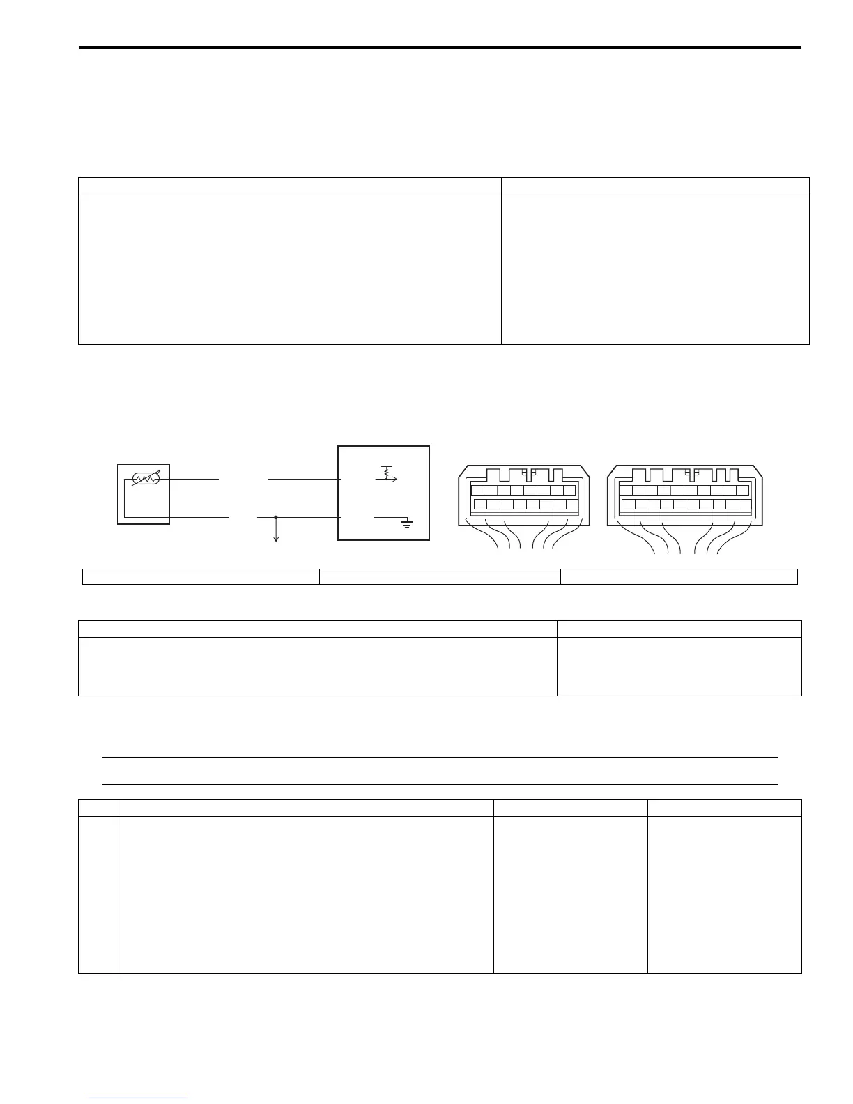
Wiring Diagram
DTC Detecting Condition and Trouble Area
DTC Troubleshooting
NOTE
When DTC B1503, B1513 and B1514 are indicated together, it is possible that “ORN” wire circuit open.
Inspection item Correction
• Refrigerant ---- leakage and amount
• A/C pipe or hose ---- disconnection, looseness and deterioration
• A/C compressor drive belt ---- looseness and damage Refer to “Compressor Drive Belt Inspection and
Adjustment”.
• Battery ---- fluid level and corrosion of terminal
• Connectors of electric wire harness ---- disconnection and friction
• Fuses ---- burning
• Parts ---- installation and damage
• Other parts that can be checked visually
5V
PNK/BLK
ORN
G52-6
G52-3
2
1
3
78
12
910
65 43
1516 14 13 12 11
G52
78
910
1920
12
1112
65 43
1718 16 15 14 13
G51
I5RS0A722010-01
1. HVAC control module 2. Inside air temperature sensor 3. To other sensors
DTC Detecting Condition Trouble Area
Inside air temperature sensor signal voltage is higher than or lower than
specified value for specified time continuously.
• Inside air temperature sensor circuit
• Inside air temperature sensor
• HVAC control module
Step Action Yes No
1 Inside air temperature sensor signal circuit check
1) Disconnect inside air temperature sensor connector.
2) Check for proper connection to inside air temperature
sensor at “PNK/BLK” and “ORN” wire terminals.
3) If OK, measure voltage between “PNK/BLK” wire
terminal of inside air temperature sensor connector and
vehicle body ground with ignition switch turned ON.
Is voltage 4 – 6 V?
Go to Step 5. Go to Step 2.

 Loading...


