4F-36 Electronic Stability Program:
DTC C1034: Yaw Rate / G Sensor Assembly Power Supply Failure
S7RS0B4604032
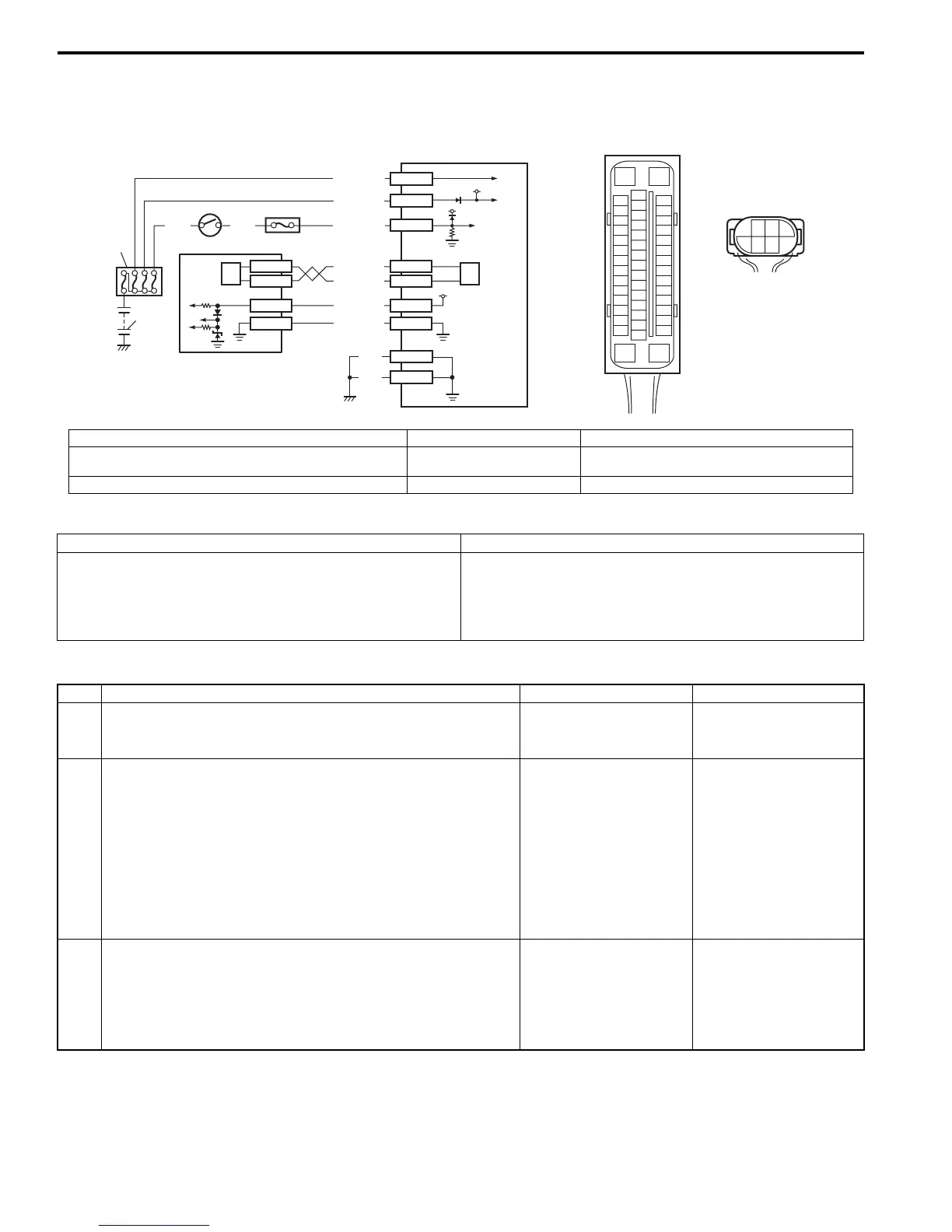
Wiring Diagram
DTC Detecting Condition and Trouble Area
DTC Troubleshooting
[A]
E85
16
1
15
2
3
4
5
6
7
8
9
10
11
12
13
14
17
18
19
20
21
22
23
24
25
26
27
28
29
30
31
32
33
34
35
36
37
38
39
40
41
42
43
44
45
46
47
[B]
E84
3
5
21
46
1
E85-16
E85-47
12V
12V
E85-32
E85-1
E85-35
GRNWHT
WHT/RED
WHT/BLU
E85-29
E85-25
E85-37
E85-31
E84-3
E84-5
RED/BLK
BLK
BLK
WHT/BLK
E84-2
E84-1
12V
GRN/BLK
BLU/RED
2
3
5
6
4
7
6
GRN/ORN
I7RS0B460009-01
[A]: ESP® control module connector (viewed from terminal side) 2. Main fuse box 5. Yaw rate / G sensor assembly
[B]: Yaw rate / G sensor assembly connector (viewed from
harness side)
3. Ignition switch 6. CAN driver
1. Battery 4. Junction block assembly 7. ESP® hydraulic unit / control module assembly
DTC Detecting Condition Trouble Area
• Power supply voltage of yaw rate / G sensor assembly
is too high when ignition switch OFF.
• Power supply voltage of yaw rate / G sensor assembly
is too low when ignition switch ON.
• Yaw rate / G sensor assembly power supply circuit
• ESP® control module power supply circuit
• Yaw rate / G sensor assembly
• ESP® control module
Step Action Yes No
1 Was “Electronic Stability Program Check” performed? Go to Step 2. Go to “Electronic
Stability Program
System Check”.
2 Check yaw rate / G sensor assembly ground circuit
1) Turn ignition switch to OFF position.
2) Disconnect yaw rate / G sensor assembly connector.
3) Check for proper connection to yaw rate / G sensor
assembly connector terminals at “E84-3” and “E84-5”.
4) If OK, then measure voltage between connector terminal
“E84-3” and vehicle body ground.
Is it 0 V?
Go to Step 3. Go to Step 4.
3 Check yaw rate / G sensor assembly power supply
circuit
1) Measure voltage between connector terminal “E84-3”
and “E84-5” with ignition switch turned ON.
Is it 10 – 14 V?
Substitute a known-
good yaw rate / G
sensor assembly and
recheck.
Go to Step 4.

 Loading...


