Electronic Stability Program: 4F-23
ABS Warning Lamp Does Not Come ON at Ignition Switch ON
S7RS0B4604048
Wiring Diagram
4 Check ESP® control module power supply circuit
1) Turn ignition switch to OFF position.
2) Check for proper connection to ESP® control module
connector at terminals “E85-1” and “E85-32”.
3) If OK, then turn ignition switch to ON position and
measure voltage between each terminal of “E85-1”,
“E85-32” and vehicle body ground.
Are they 10 – 14 V?
Go to Step 5. “WHT/BLU” and/or
“WHT/RED” circuit
open.
5 Check ESP® control module ground circuit
1) Turn ignition switch to OFF and measure resistance
between each terminal of “E85-16”, “E85-47” and vehicle
body ground.
Is resistance less than 2
Ω
?
Go to Step 6. Ground circuit for ESP®
control module open or
high resistance.
6 CAN communication circuit check
1) Check CAN communication circuit between combination
meter and ESP® control module referring to “DTC
U1073: Control Module Communication Bus Off”.
Is CAN communication circuit in good condition?
Substitute a known-
good combination meter
and recheck. If warning
lamp remains ON,
substitute a known-
good ESP® hydraulic
unit / control module
assembly and recheck.
Repair or replace.
Step Action Yes No
[A]
E85
16
1
15
2
3
4
5
6
7
8
9
10
11
12
13
14
17
18
19
20
21
22
23
24
25
26
27
28
29
30
31
32
33
34
35
36
37
38
39
40
41
42
43
44
45
46
47
WHT
GRN
3
E85-13
E85-44
RED
WHT
6
5
E46-1
E46-2
4
10
6
E85-16
E85-47
BLK
BLK
8
9
BLK/ORN
RED
WHT
RED
WHT
G37-4
G37-2
G28-10
G28-8
G28-16
12V
12V
E85-32
E85-1
E85-35
WHT/RED
WHT/BLU
GRN/ORN
6
2
1
7
11
12
[B]
G37E46
1245367
891011121314
1245367
891011
1213141516171819202122
[C]
G28
12345678910111213141516
17181920212223242526272829303132
G28-31
RED/BLK
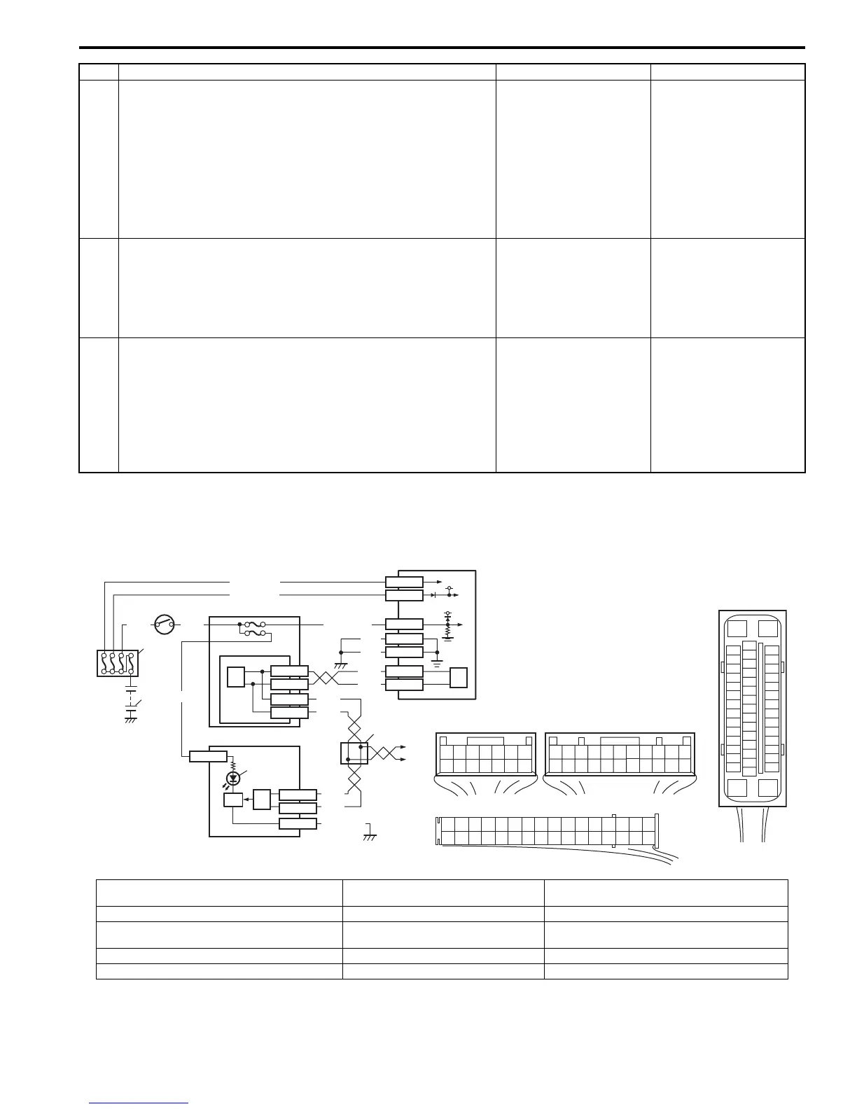
I6RS0B460010-01
[A]: ESP® control module connector (viewed
from terminal side)
3. Ignition switch 8. ABS warning lamp
[B]: BCM connector (viewed from harness side) 4. Junction block assembly 9. Lamp driver module
[C]: Combination meter connector (viewed from
harness side)
5. BCM (included in junction block
assembly)
10. ESP® hydraulic unit / control module
assembly
1. Battery 6. CAN driver 11. Junction connector
2. Main fuse box 7. Combination meter 12. To steering angle sensor

 Loading...


