1H-8 Ignition System:
Ignition Coil Assembly (Including ignitor)
Removal and Installation
S7RS0B1806005
Removal
1) Disconnect negative (–) cable at battery.
2) Remove air cleaner assembly with air intake pipe
and cylinder head upper cover.
3) Disconnect ignition coil coupler.
4) Disconnect high-tension cord (3) from ignition coil
assembly (2).
5) Remove ignition coil bolts (1) and then pull out
ignition coil assembly.
Installation
1) Install ignition coil assembly (2).
2) Tighten ignition coil bolts (1) to specified torque, and
then connect ignition coil coupler.
Tightening torque
Ignition coil bolt (a): 10 N·m (1.0 kgf-m, 7.5 lb-ft)
3) Install high-tension cord (3) to ignition coil assembly
while gripping its cap.
4) Install cylinder head upper cover and air cleaner
assembly with air intake pipe.
5) Connect negative (–) cable to battery.
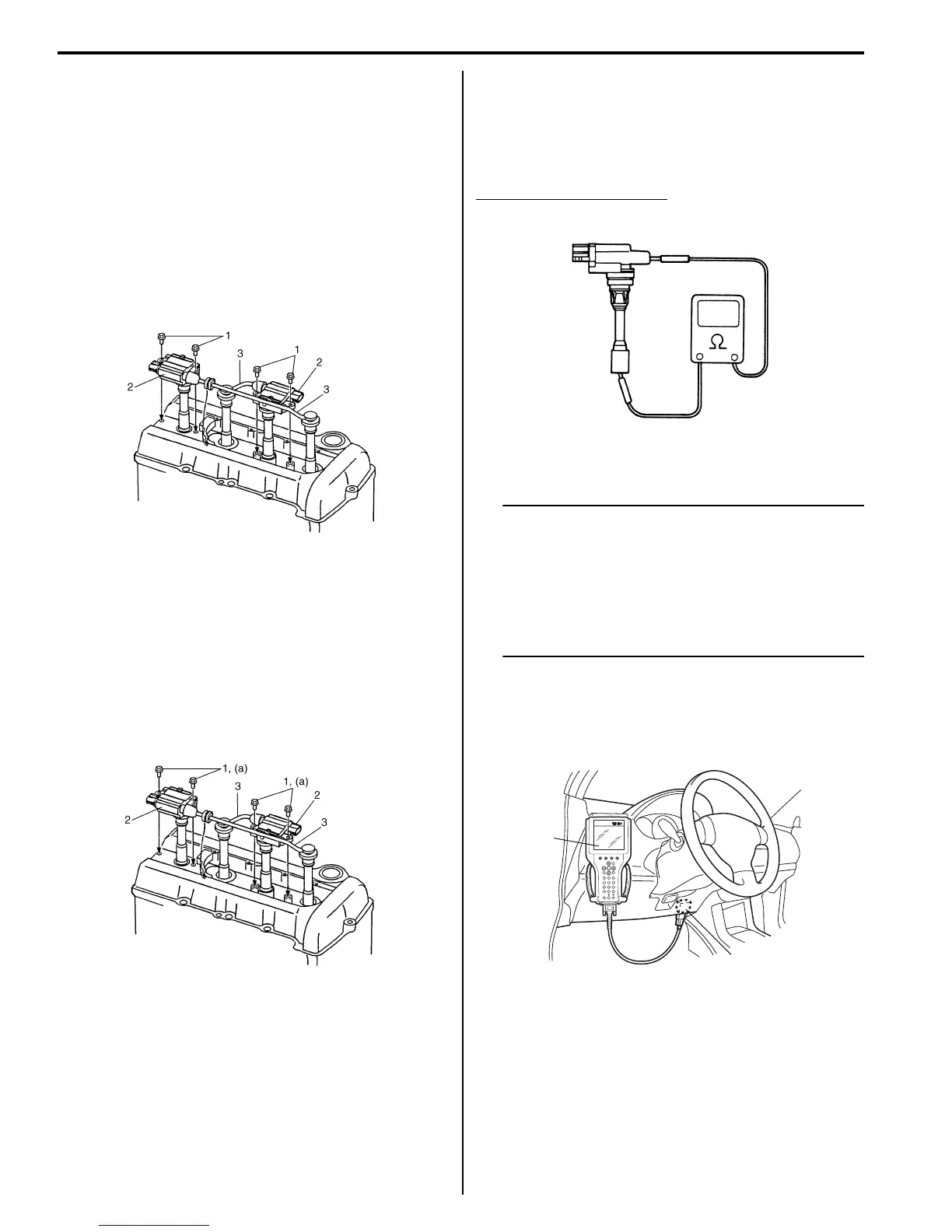
Ignition Coil Assembly (Including ignitor)
Inspection
S7RS0B1806006
Measure secondary coil for resistance.
If resistance is out of specification, replace ignition coil
assembly.
Secondary coil resistance
7.5 – 10.3 kΩ at 20 °C, 68 °F
Ignition Timing Inspection
S7RS0B1806007
NOTE
• Ignition timing is not adjustable. If ignition
timing is out of specification, check
system related parts.
• Before starting engine, place transmission
gear shift lever in “Neutral” (shift selector
lever to “P” range for A/T model), and set
parking brake.
1) Connect scan tool to DLC (1) with ignition switch
OFF.
Special tool
(A): SUZUKI scan tool
2) Start engine and warm it up to normal operating
temperature.
3) Make sure that all of electrical loads except ignition
are switched off.
4) Check to be sure that idle speed is within
specification referring to “Idle Speed and IAC
Throttle Valve Opening Inspection in Section 1A”
5) Fix ignition timing by using “Fixed Spark” of “Misc
Test” mode on scan tool.
I2RH0B180006-01
I3RM0A180004-01
I2RH0B180007-01
(A)
1
I4RS0B180003-01

 Loading...


