7B-62 Air Conditioning System: Automatic Type
DTC B1541: HVAC Control Module Back-Up Power Supply Malfunction
S7RS0B7224017
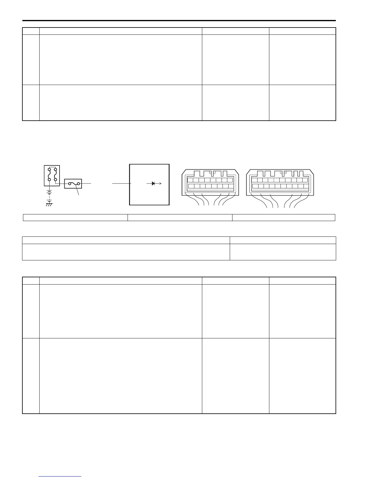
Wiring Diagram
DTC Detecting Condition and Trouble Area
DTC Troubleshooting
11 Position sensor circuit check
1) Check air flow control actuator position sensor circuit
referring to Step 1 to Step 5 and Step 10 to Step 11 of
“DTC B1512: Air flow Control Actuator (Position Sensor)
and/or Its Circuit Malfunction”.
Is it in good condition?
Go to Step 12. Repair circuit.
12 Air flow control actuator check
1) Check air flow control actuator referring to “Air Flow
Control Actuator Inspection”.
Is it in good condition?
HVAC control module
faulty.
Air flow control actuator
faulty.
Step Action Yes No
WHT/RED
2
1
78
12
910
65 43
1516 14 13 12 11
G52
78
910
1920
12
1112
65 43
1718 16 15 14 13
G51
3
G52-16
I5RS0A722015-01
1. HVAC control module 2. Junction block assembly 3. Circuit fuse
DTC Detecting Condition Trouble Area
Back-up power supply voltage is lower than specified value continuously. • Battery voltage supply circuit
• HVAC control module
Step Action Yes No
1 DTC check
1) Turn ON ignition switch for 20 sec. or more.
2) Ignition switch turned OFF and connect scan tool to
DLC.
3) Turn ON ignition switch and check DTC.
Is there DTC B1541?
Go to Step 2. Intermittent trouble.
Check for intermittent
referring to “Intermittent
and Poor Connection
Inspection in Section
00”.
2 Battery voltage supply circuit check
1) Disconnect connector from HVAC control module with
ignition switch turned OFF.
2) Check for proper connection to HVAC control module
connector at “G52-16” terminal.
3) If OK, measure voltage between “G52-16” terminal of
HVAC control module connector and vehicle body
ground.
Is voltage 10 – 14 V?
HVAC control module
faulty.
Circuit fuse blown and/
or “WHT/RED” wire
circuit open or short.

 Loading...


