4B-4 Front Brakes:
Installation
1) Torque caliper pin bolts (a) to specification.
NOTE
• Make sure that boots are fit into groove
securely.
• If brake pads are replaced, use new caliper
pin bolts included in repair kit. (if included)
Tightening torque
Caliper pin bolt (a): 26 N·m (2.6 kgf-m, 19.0 lb-ft)
2) Connect caliper to flexible hose.
3) Torque flexible hose joint bolt to specification.
Tightening torque
Flexible hose joint bolt (b): 23 N·m (2.3 kgf-m,
17.0 lb-ft)
WARNING
!
Make sure that flexible hose is not twisted
when tightening joint bolt. If it is twisted,
reconnect it using care not to twist it.
4) Tighten bleeder plug to specified torque.
Tightening torque
Bleeder plug (c): 8.0 N·m (0.8 kgf-m, 6.0 lb-ft)
5) Lower hoist and torque wheel nuts to specifications.
Tightening torque
Wheel nut: 85 N·m (8.5 kgf-m, 61.5 lb-ft)
6) After completing installation, fill reservoir with brake
fluid and bleed air from brake system referring to “Air
Bleeding of Brake System in Section 4A”.
7) Check each installed part for fluid leakage.
8) Perform brake test and check fluid leakage.
Front Disc Brake Caliper Disassembly and
Assembly
S7RS0B4206006
Disassembly
CAUTION
!
• Clean around caliper with brake fluid
before disassembly.
• Be careful not to damage inside (bore side)
of cylinder.
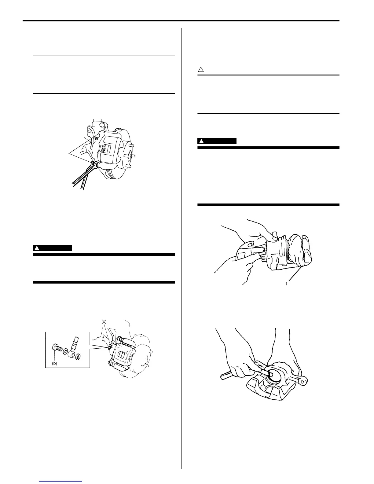
1) Remove piston with air blown into flexible hose bolt
installation hole.
WARNING
!
Do not apply too highly compressed air
which will cause piston to jump out of
cylinder. Place a cloth (1) to prevent piston
from damage. It should be taken out
gradually with moderately compressed air.
Do not place your fingers in front of piston
when using compressed air.
2) Remove cylinder boot.
3) Remove piston seal using a thin blade like a
thickness gauge, etc.
4) Remove bleeder plug and cap from caliper.
(a)
I4RS0A420003-01
I6RS0C420004-01
I2RH01420011-01
I2RH01420013-01

 Loading...


