Power Assisted Steering System: 6C-35
Inspection of P/S Control Module and Its Circuits
S7RS0B6304023
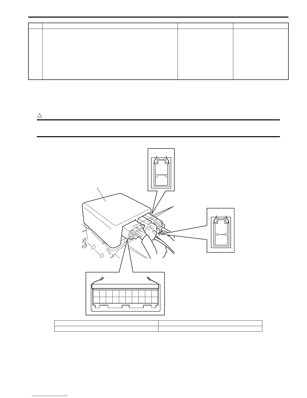
The P/S control module (1) and its circuits can be checked at the P/S control module wiring couplers (2) by measuring
voltage and resistance.
CAUTION
!
P/S control module cannot be checked by itself. It is strictly prohibited to connect voltmeter or
ohmmeter to the P/S control module with connectors disconnected from the P/S control module.
5 P/S control module ground circuit check
1) Connect connectors to P/S control module.
2) Start engine.
3) Measure voltage between “E49-2” terminals of P/S
control module connector and body ground when
steering wheel fully turned to left or right.
Is voltage 0.3 V or less?
P/S Control Module
Power Supply and
Ground Circuit is in
good condition.
“BLK” wire is open or
high resistance circuit.
Step Action Yes No
[A]
12
3
4
5
67
8
9
11
10
12 13
14
15
16
17 18 19
20
[B]
[C]
1
2
1
1
2
2
I6RS0C630016-03
[A]: Connector “E52” (viewed from harness side) [C]: Connector “E49” (viewed from harness side)
[B]: Connector “E51” (viewed from harness side)

 Loading...


