4F-62 Electronic Stability Program:
4) Turn ignition switch to ON position and select menu
“DATA LIST” mode of SUZUKI scan tool. Refer to
scan tool operator's manual for further derails.
5) When brake pedal is released, check “Master Cyl
Press” under “DATA LIST” of SUZUKI scan tool.
If pressure is out of specification, replace ESP®
hydraulic unit / control module assembly.
Master cylinder pressure specification
Brake pedal released: 0 ± 0.8 MPa (0 ± 8 kg/cm
2
, 0
± 113 psi)
6) Hoist vehicle and remove right-side front wheel.
7) Connect special tool with rubber hose (1) to Front
brake caliper bleeder plug (2).
Special tool
(A): 09956–02311
8) When bleeder plug loosen and depress brake pedal
to make special tool gauge reading 10 MPa (100 kg/
cm
2
, 1422 psi), check “Master Cyl Press” under
“DATA LIST” of SUZUKI scan tool.
If pressure displayed on SUZUKI scan tool is out of
specification, replace ESP® hydraulic unit / control
module assembly.
Master cylinder pressure specification
Brake pedal depressed 10 MPa (100 kg/cm
2
, 1422
psi): 10 ± 1.2 MPa (100 ± 12 kg/cm
2
, 1422 ± 170
psi)
9) After completing the check, turn ignition switch to
OFF position and disconnect SUZUKI scan tool from
DLC.
10) Tighten bleeder plug and bleed air from brake
system, referring to “Air Bleeding of Brake System in
Section 4A”.
Yaw Rate / G Sensor Assembly On-Vehicle
Inspection
S7RS0B4606017
Lateral G Inspection
1) Calibrate yaw rate / G sensor assembly referring to
“Sensor Calibration”.
2) Park and level the vehicle with parking brake and fix
wheels with chokes.
3) Check yaw rate / G sensor assembly installation
condition.
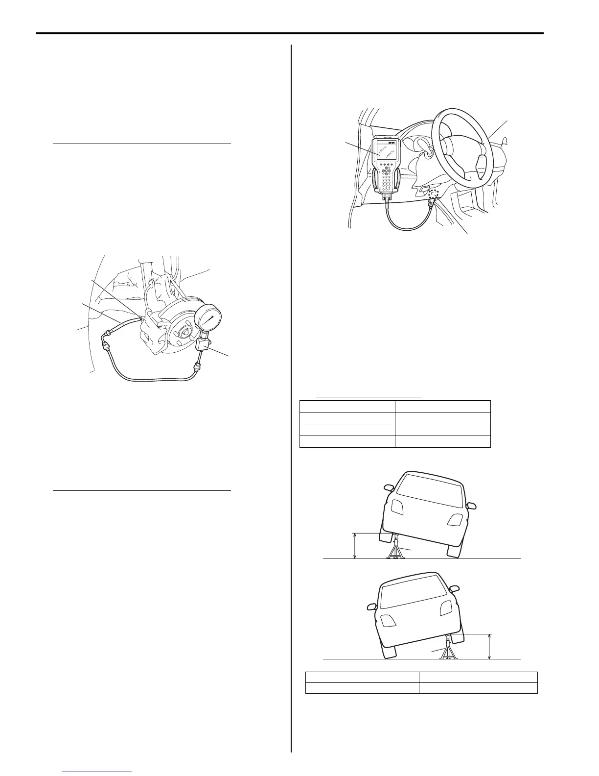
4) Connect SUZUKI scan tool to data link connector
(DLC) (1) with ignition switch OFF.
Special tool
(A): SUZUKI scan tool
5) Turn ignition switch to ON position and select menu
“DATA LIST” mode of SUZUKI scan tool. Refer to
scan tool operator's manual for further derails.
6) Check “G Sensor (lateral)” under “DATA LIST” of
SUZUKI scan tool in the following vehicle conditions.
• Level condition
• Right-up condition
• Left-up condition
If Lateral G condition is out of specification, replace
yaw rate / G sensor assembly.
Lateral G specification
2
(A)
1
I6JB01460025-01
Vehicle condition G Sensor (lateral)
Level condition 0 ± 0.1 G
Right-up condition 0.1 ± 0.1 G
Left-up condition –0.1 ± 0.1 G
[A]: Right-up condition “a”: Approx 350 mm (13.78 in.)
[B]: Left-up condition 1. Safety stand
(A)
1
I4RS0B450003-01
[A]
[B]
“a”
1
“a”
1
I6RS0B460039-02

 Loading...


