Power Assisted Steering System: 6C-15
“EPS” Warning Light Does Not Come ON with Ignition Switch Turned ON before Engine Starts
S7RS0B6304010
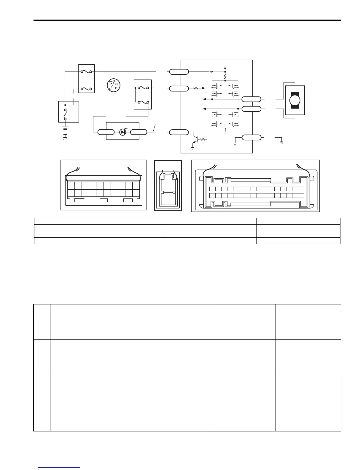
Wiring Diagram
Circuit Description
Operation (ON/OFF) of “EPS” warning light is controlled by P/S control module through combination meter.
If the P/S system is in good condition, P/S control module turns “EPS” warning light ON at the ignition switch ON, and
then turns it OFF at the engine start. If an abnormality in the system is detected, “EPS” warning light is turned ON
continuously by P/S control module. If P/S control module is disconnected, “EPS” warning light is not turned ON.
Troubleshooting
M
BLK
RED
E51-1
E51-2
[A]
12
3
4
5
67
8
9
11
10
12 13
14
15
16
17 18 19
20
10 9 8 7 654321
16 15 14 13 12 11
26 25 24 23 22 21 20 19 18 17
32 31 30 29 28 27
[C]
7
12V
E49-2
BLK
[B]
1
2
GRY
LT GRN
/BLK
E52-1
E52-5
E49-1
GRN
GRN
WHT
BLK
WHY
G28-25G28-31
RED/BLK
8
3
4
4
5
6
4
4
1
2
4
9
I7RS0B630004-01
[A]: Connector “E52” (viewed from harness side) 2. Ignition switch 6. “EPS” warning light
[B]: Connector “E49” (viewed from harness side) 3. Junction block assembly 7. P/S control module
[C]: Connector “G28” (viewed from harness side) 4. Fuse 8. Individual circuit fuse box No.1
1. Main fuse box 5. Combination meter 9. “EPS” warning light circuit
Step Action Yes No
1 1) Turn ignition switch ON.
Do the other warning lights come on?
Go to Step 2. “GRN”, “RED/BLK” wire
circuit or circuit fuse for
combination meter open
or short to ground.
2 1) Check power supply circuit and ground circuit for P/S
control module referring to “P/S Control Module Power
Supply and Ground Circuit Check”.
Is check result in good condition?
Go to Step 3. Repair or replace
defective circuit.
3 1) Remove combination meter and disconnect combination
meter connector (“G28”) with ignition switch turned OFF.
2) Check for proper connection to the combination meter at
“G28-31” terminal.
3) If OK, check voltage between “G28-31” (“RED/BLK”
wire) terminal and body ground with ignition switch ON.
Is it 10 – 14 V?
Go to Step 4. “RED/BLK” wire circuit
open or short to ground.

 Loading...


