Air Conditioning System: Automatic Type 7B-47
Scan Tool Data Definitions
TEMP CONT SWITCH (TEMPERATURE
SELECTOR): Position of temperature control
selector of HVAC control module
CABIN TEMPERATURE: In-car temperature detected
by inside air temperature sensor installed in HVAC
control module
OUTSIDE AIR TEMP (OUTSIDE AIR
TEMPERATURE): Outside air temperature
detected by outside air temperature sensor installed
in front bumper member
EVAPORATOR TEMP (EVAPORATOR
TEMPERATURE): Temperature of air passed
through evaporator
COOLANT TEMP (ENGINE COOLANT
TEMPERATURE): Engine coolant temperature
detected by engine coolant temperature sensor
SUN LOAD: Amount of sunlight detected by sunload
sensor installed on the driver side on the dashboard
MODE CONT SWITCH (MODE (AIR FLOW)
SELECTOR): Position of air flow selector of HVAC
control module
FAN CONT SWITCH (BLOWER SPEED SELECTOR):
Position of blower speed selector of HVAC control
module
FAN DESIRED VOLT: Voltage for blower motor
AIR MIX POS SEN (TEMPERATURE CONTROL
ACTUATOR POSITION SENSOR): Input signal
from position sensor in temperature control actuator
MODE POS SENSOR (AIR FLOW CONTROL
ACTUATOR POSITION SENSOR): Input signal
from position sensor in air flow control actuator
A/C CONT SIG (A/C SWITCH SIGNAL, ON or OFF):
State of A/C switch
BLOWER LOAD SIG (BLOWER FAN LOAD SIGNAL,
ON or OFF): ON: Position of blower speed selector
is 1st position or more / OFF: Position of blower
speed selector is OFF position.
AIR INTAKE MODE (AUTO, FRE or REC): State of air
intake mode
REFRIGERANT PRESSURE (A/C REFRIGERANT
ABSOLUTE PRESSURE): This parameter
indicates A/C refrigerant absolute pressure
calculated by ECM
A/C COMP CLUTCH (A/C COMPRESSOR MAGNET
CLUTCH, ON or OFF): This parameter indicates
the state of the A/C switch
DFR INDICATOR (DEFROSTER INDICATOR LAMP,
ON or OFF): State of defroster indicator lamp
VEHICLE SPEED: It is computed based on pulse
signals from vehicle speed sensor
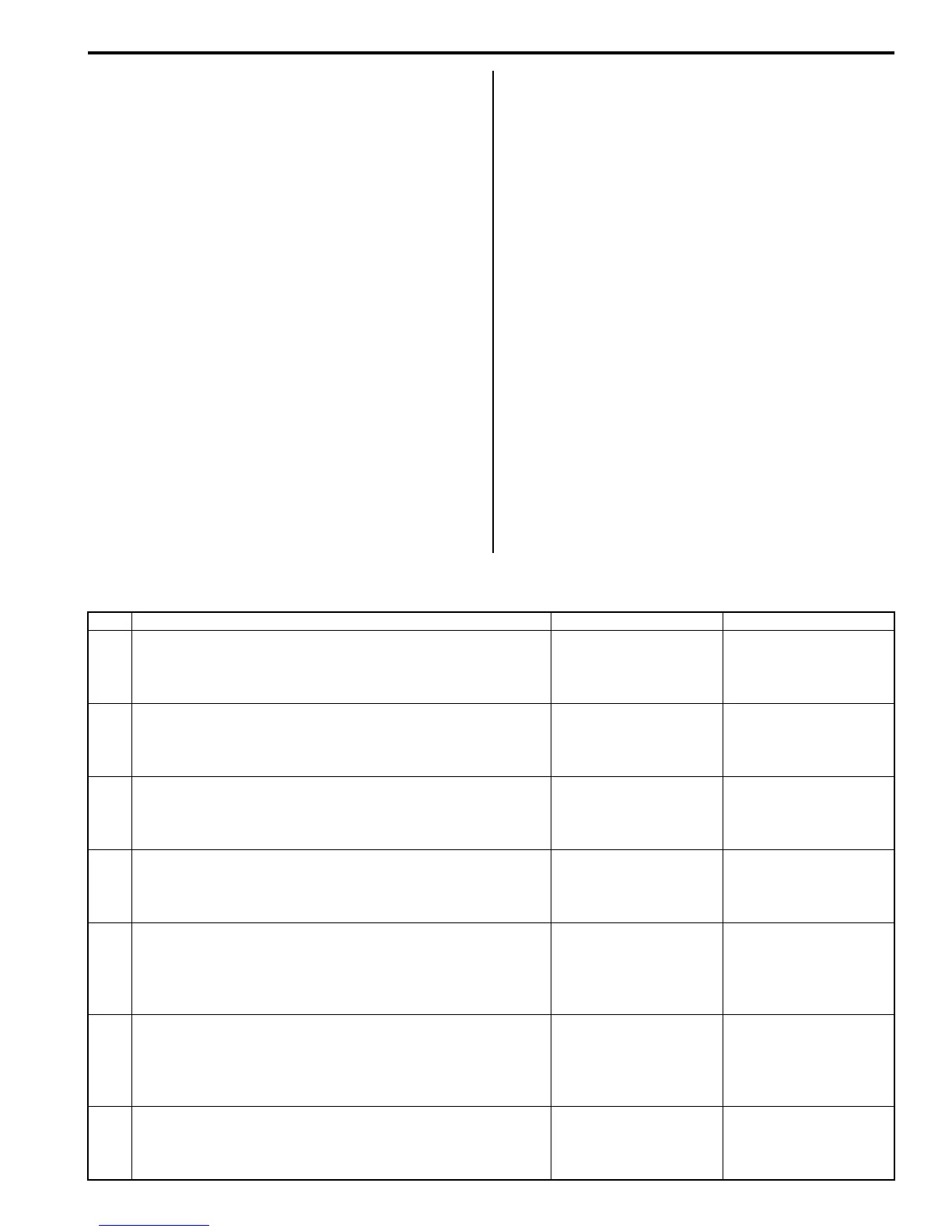
Air Conditioning System Check
S7RS0B7224008
Step Action Yes No
1 Customer complaint analysis
1) Perform )”Customer complaint analysis”.
Was customer complaint analysis performed?
Go to Step 2. Perform customer
complaint analysis.
2 Visual inspection
1) Perform )“Visual inspection”.
Is there any faulty condition?
Repair or replace
malfunction part.
Go to Step 3.
3 DTC check
1) Perform )“DTC check”.
Is there any DTC code?
Go to Step 4. Go to Step 5.
4 Troubleshooting malfunction
1) Perform ) “Troubleshooting malfunction”.
Is there any faulty condition?
Repair or replace
malfunction part, and go
to Step 7.
Go to Step 5.
5 Perform A/C system symptom diagnosis
1) Inspect and repair referring to “A/C System Symptom
Diagnosis”.
Is there any faulty condition?
Repair or replace
malfunction part, and go
to Step 7.
Go to Step 6.
6 Check for intermittent problem
1) Check for intermittent troubles referring to “Intermittent
and Poor Connection Inspection in Section 00”.
Is there any faulty condition?
Repair or replace
malfunction part, and go
to Step 7.
Go to Step 7.
7 Final confirmation test
1) Perform ) “Final confirmation test”.
Is there any malfunction code?
Go to Step 4. End.

 Loading...


