9F-10 Security and Locks:
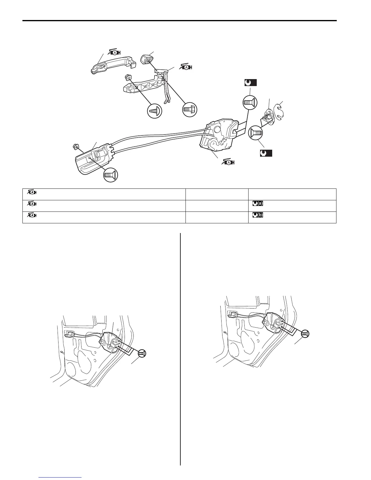
Rear Door Lock Assembly Components
S7RS0B9606007
Rear Door Lock Assembly Removal and
Installation
S7RS0B9606008
Removal
1) Remove rear door glass referring to “Rear Door
Glass Removal and Installation in Section 9E”.
2) Disconnect door lock motor lead wire.
3) Remove door latch mounting screws (1) and remove
door latch assembly (2).
Installation
Reverse removal procedure to install rear door lock
assembly referring to the following instruction and “Front
Door Lock Assembly Removal and Installation”.
• Tighten door latch screw to specified torque.
Tightening torque
Door latch screw (a): 5.0 N·m (0.5 kgf-m, 4.0 lb-ft)
Rear Door Lock Assembly Inspection
S7RS0B9606009
• Check that door opens and closes smoothly and
properly.
• Check that door stops in the secondary latched
position properly (preventing door from opening
freely) and that door closes completely in the fully
latched position.
• Adjust door latch striker position, if necessary.
(a)
(b)
1
7
2
6
3
4
5
I4RS0A960012-02
1. Outside handle
: Apply lithium grease 99000-25010 to sliding part.
4. Latch striker 7. Out side handle cap
2. Outside handle frame
: Apply lithium grease 99000-25010 to sliding part and spring.
5. Shim : 5.0 N⋅m (0.5 kgf-m, 4.0 lb-ft)
3. Rear door latch assembly
: Apply lithium grease 99000-25010 to sliding part.
6. Inside handle bezel : 10 N⋅m (1.0 kgf-m, 7.5 lb-ft)
1
2
I4RS0A960013-01
(a)
I4RS0A960014-01

 Loading...


