Keyless Start System: 10E-25
DTC No. 31: Lost Communication with BCM
S7RS0BA504020
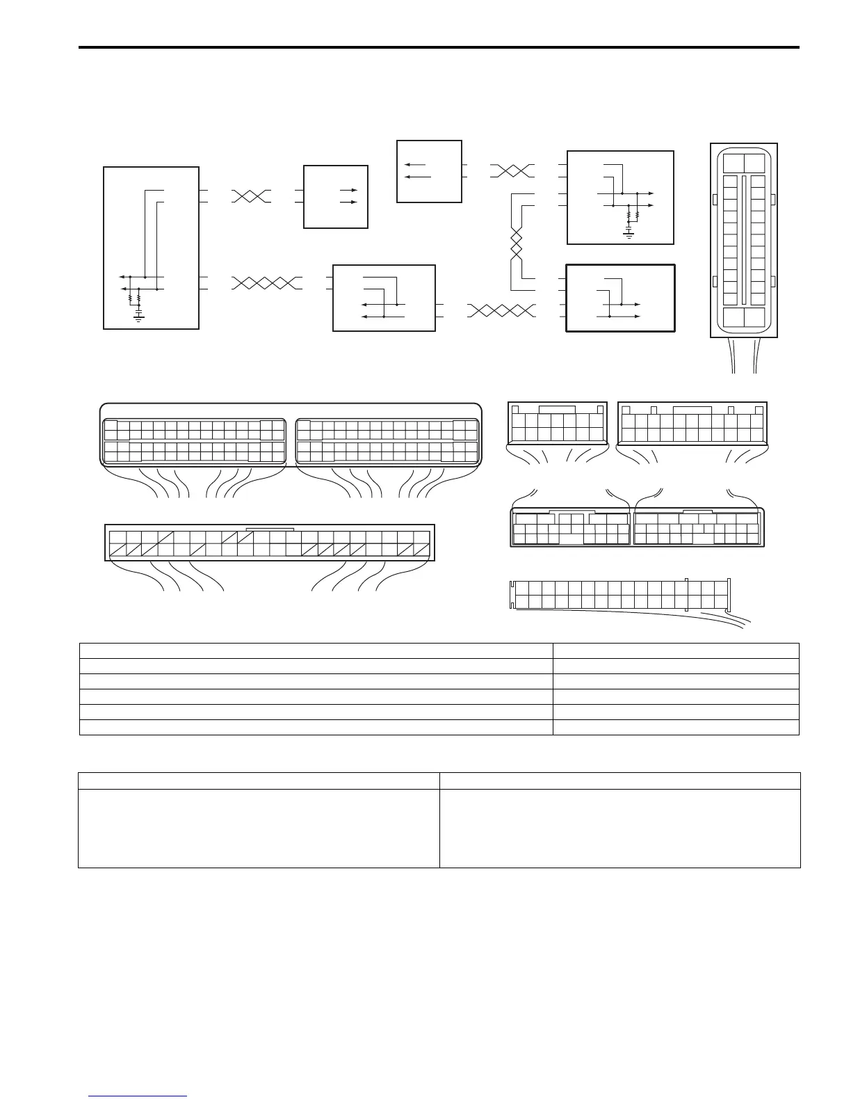
Wiring Diagram
DTC Detecting condition and trouble area
DTC Confirmation Procedure
1) Clear DTC referring to “DTC Clearance”.
2) Turn ignition key knob by pushing ignition key knob.
3) Check DTC referring to “DTC Check”.
RED
WHT
E03-12
E03-6
RED
WHT
E03-10
E03-8
RED
WHT
RED
WHT
G42-19
G42-18
3
RED
WHT
RED
WHT
RED
WHT
RED
WHT
RED
WHT
E46-1
G37-4
G42-19
G42-18
G28-8
G28-10
G37-2
C34-7
E46-2
C34-17
1
2
4
53
21
[A]
E23
G42
C37
34
1819
5671011
17
20
47 46
495051
2122
52
16
25
9
24
14
29
5557 5453
59
60
58
2
262728
15
30
56
48
32 31343536374042 3938
44
45 43 41 33
11213
23
834
1819
5671011
17
20
47 46
495051
2122
52
16
25
9
24
14
29
5557 5453
59
60
58
26
27
28
15
30
56
48
32 31343536374042 3938
44
45 43 41 33
1213
23
8
[B]
[D]
[C]
65
1615141312 11
43
2423 2122
10 9 8 7
21
1920 1817
C34
1716
2625
15 14
65 342
1312
232224
1110 9
212019
87
18
1
C35
[E]
G28
12345678910111213141516
17181920212223242526272829303132
1245367
891011
1213141516171819202122
G37
E46
1245367
891011121314
1234567891011141516
36 34 33 32 31 30 29 24 2337
181920
G28-9
G28-7
RED
WHT
E23-3
E23-18
RED
WHT
C37-13
C37-12
6
[F]
E03
15
16
17
18
19
20
21
22
23
24
25
2
3
4
5
6
7
8
9
10
11
12
1
13
14
26
I6RS0CA50002-01
[A]: ECM connector (viewed from harness side) 1. ECM
[B]: Keyless start control module connector (viewed from harness side) 2. TCM (A/T model)
[C]: BCM connector (viewed from harness side) 3. Keyless start control module
[D]: TCM connector (A/T model) (viewed from harness side) 4. BCM
[E]: Combination meter connector (viewed from harness side) 5. Combination meter
[F]: ABS control module connector (viewed from terminal side) 6. ABS control module
DTC detecting condition Trouble area
Keyless start control module cannot receive data sent by
CAN from BCM
• CAN communication circuit
• Keyless start control module
• Combination meter
•BCM

 Loading...


