4F-42 Electronic Stability Program:
DTC C1061: Pump Motor and/or Motor Driver Circuit Failure
S7RS0B4604054
Wiring Diagram
DTC Detecting Condition and Trouble Area
5 Check power supply circuit from battery
1) Measure voltage between terminals “E85-1” and “E85-
16”, “E85- 47" with engine running.
Are voltage 18
±
1.0 V or less?
Poor connection of
“E85-1”, “E85-16” and/
or “E85-47” terminals. If
the terminals are in
good condition,
substitute a known-
good ESP® hydraulic
unit / control module
assembly and recheck.
Check charging system
referring to “Generator
Test (Overcharged
Battery Check) in
Section 1J”.
Step Action Yes No
[A]
E85
16
1
15
2
3
4
5
6
7
8
9
10
11
12
13
14
17
18
19
20
21
22
23
24
25
26
27
28
29
30
31
32
33
34
35
36
37
38
39
40
41
42
43
44
45
46
47
4
5
1
2
WHT/RED
3
12V
M
12V
BLK
BLK
E85-16
E85-47
E85-32
I6RS0B460024-02
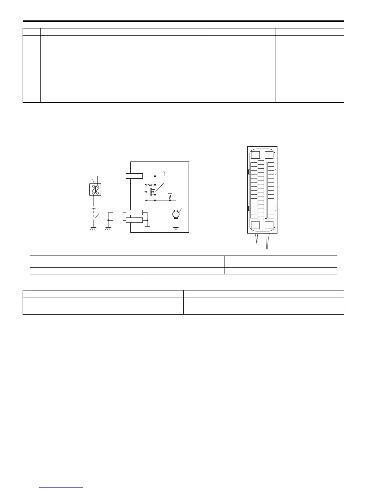
[A]: ESP® control module connector (viewed from
terminal side)
2. Main fuse box 4. Pump motor
1. Battery 3. Pump motor driver (transistor) 5. ESP® hydraulic unit / control module assembly
DTC Detecting Condition Trouble Area
Defective pump motor and/or motor power supply voltage
is too low.
• Pump Motor and/or Motor Driver power supply circuit
• ESP® control module

 Loading...


