1A-194 Engine General Information and Diagnosis:
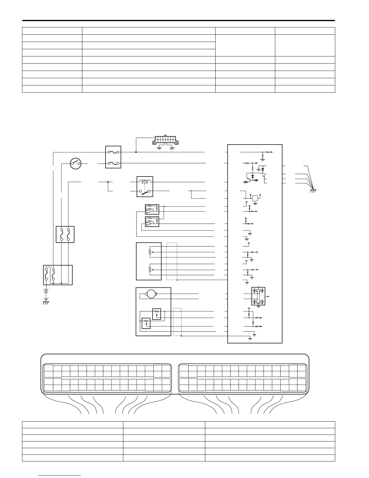
ECM Power and Ground Circuit Check
S7RS0B1104080
Wiring Diagram
C37-3 to E23-1/16 EGR valve (stepping motor No.2 coil)
20 – 31 Ω —C37-18 to E23-1/16 EGR valve (stepping motor No.4 coil)
C37-19 to E23-1/16 EGR valve (stepping motor No.3 coil)
C37-46 to E23-29 Heater of HO2S-1 2 – 11 Ω —
C37-1 to E23-1/16 No.1 fuel injector 10.8 – 18.2 Ω —
E23-47 to E23-1/16 A/C compressor relay 160 – 240 Ω —
C37-60 to C37-59 Oil control valve 6 – 15 Ω —
E23-45 to E23-1/16 Throttle actuator control relay 160 – 240 Ω —
Terminals Circuit Standard resistance Condition
E23 C37
34
1819
5671011
1720
47 46495051
2122
52
1625
9
24
14
29
5557 54 53
59
60 58
2
262728
15
30
56 48
32 31343536374042 39 38
44
45 43 41 33
11213
23
834
1819
5671011
1720
47 46495051
2122
52
1625
9
24
14
29
5557 54 53
59
60 58
2
262728
15
30
56 48
32 31343536374042 39 38
44
45 43 41 33
11213
23
8
BLK/RED
BLK/REDBLK/RED
BLK/YEL BLK/YEL
BLK/YEL
GRN
BRN/WHT
12V
5V
E23-1
E23-60
E23-16
WHT
2
4
11
6
3
12
13
14
7
1
16
17
89
15
10
5
WHT/RED
E23-2
C37-58
C37-15
C37-30
BLK/ORN
BLK
BLK
E23-31
BLK
WHT
GRY/RED
RED/BLK
ORN
C37-14
C37-53
C37-55
E23-54
RED
E23-55
GRN
BRN
BLU
RED
YEL
WHT
E23-35
E23-37
E23-52
E23-51
E23-34
E23-36
E23-50
LT GRN/RED
LT GRN/BLK
C37-45
C37-44
C37-43
C37-54
C37-40
C37-42
C37-41
RED
GRN
WHT
BLK
ORN
BLK/WHT
E23-29
I6RS0C110039-01
1. Main fuse box 7. Individual circuit fuse box No.1 13. A/C refrigerant pressure sensor (if equipped with A/C)
2. Ignition switch 8. “IG ACC” fuse 14. APP sensor (main)
3. Main relay 9. “FI” fuse 15. APP sensor (sub)
4. BCM (included in junction block assembly) 10. “RADIO” fuse 16. TP sensor (main)
5. “IG COIL” fuse 11. DLC 17. TP sensor (sub)
6. ECM 12. MAP sensor

 Loading...


