4F-40 Electronic Stability Program:
DTC C1041 / C1042 / C1043 / C1044 / C1045 / C1046 / C1051 / C1052 / C1053 / C1054 / C1055 / C1056:
Solenoid Circuit Failure
S7RS0B4604052
DTC C1041 / C1045 / C1051 / C1055: Right-Front / Left-Front / Right-Rear / Left-Rear Inlet Solenoid
Circuit Failure
DTC C1042 / C1046 / C1052 / C1056: Right-Front / Left-Front / Right-Rear / Left-Rear Outlet Solenoid
Circuit Failure
DTC C1043 / C1044: Master Cylinder Cut Solenoid Circuit No. 1 / No. 2 Failure
DTC C1053 / C1054: Low Pressure Solenoid Circuit No. 1 / No. 2 Failure
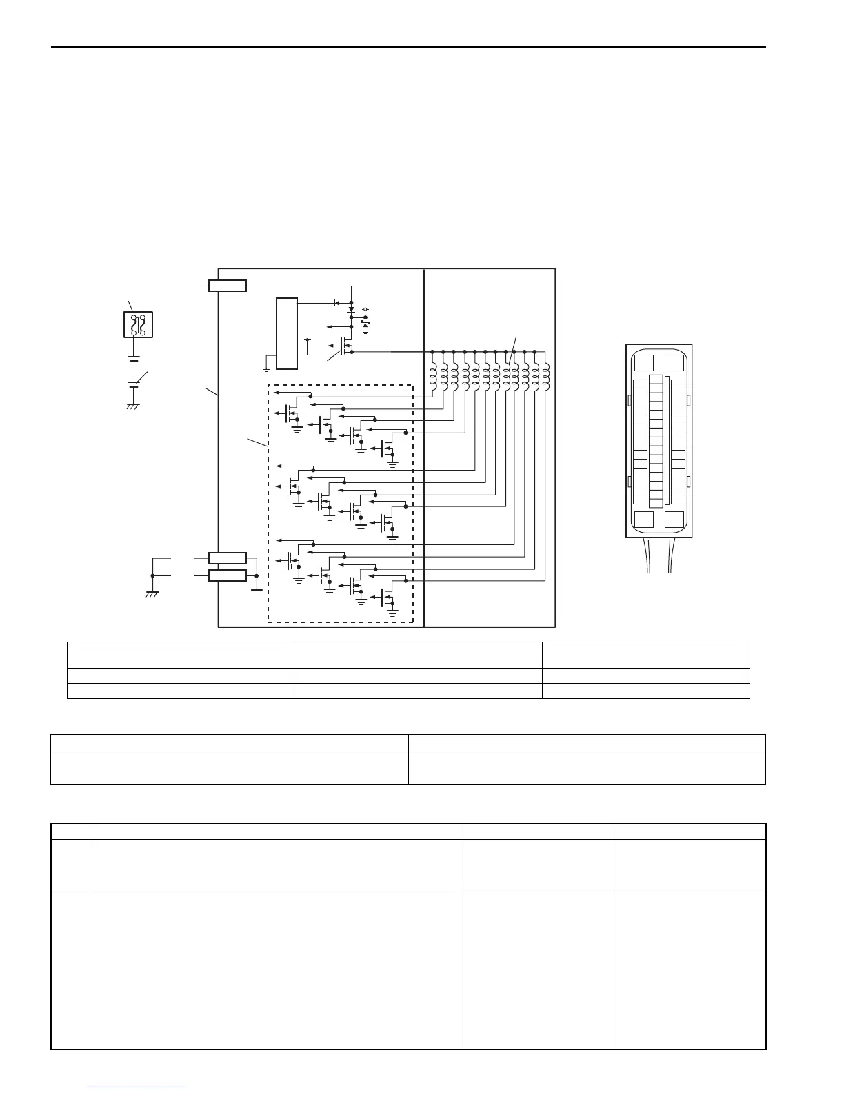
Wiring Diagram
DTC Detecting Condition and Trouble Area
DTC Troubleshooting
[A]
E85
16
1
15
2
3
4
5
6
7
8
9
10
11
12
13
14
17
18
19
20
21
22
23
24
25
26
27
28
29
30
31
32
33
34
35
36
37
38
39
40
41
42
43
44
45
46
47
WHT/BLU
1
2
5
4
BLK
BLK
5V
12V
E85-1
E85-16
E85-47
6
3
I6RS0B460021-01
[A]: ESP® control module connector (viewed
from terminal side)
3. ESP® hydraulic unit / control module assembly 6. Solenoid valve driver (transistor)
1. Battery 4. Solenoid valve
2. Main fuse box 5. Solenoid valve power supply driver (transistor)
DTC Detecting Condition Trouble Area
Mismatching solenoid output and solenoid monitor is
detected.
• ESP® control module
Step Action Yes No
1 Was “Electronic Stability Program Check” performed? Go to Step 2. Go to “Electronic
Stability Program
System Check”.
2 Check solenoid valve power supply circuit
1) Turn ignition switch to OFF position.
2) Disconnect ESP® control module connector.
3) Check for proper connection to ESP® control module
connector at terminal “E85-1”, “E85-16” and “E85-47”.
4) If OK, then measure voltage between terminal “E85-1” of
module connector and “E85-16, E85-47”.
Are they 10 – 14 V?
Substitute a known-
good ESP® hydraulic
unit /control module
assembly and recheck.
“WHT/BLU” or “BLK”
circuit open.

 Loading...


