1A-76 Engine General Information and Diagnosis:
DTC P0116: Engine Coolant Temperature Circuit Range / Performance
S7RS0B1104026
Wiring Diagram
DTC Detecting Condition and Trouble Area
8 Ground circuit check
1) Remove ECM from its bracket with ECM connectors
connected.
2) Measure resistance between “C37-55” terminal of ECM
connector and vehicle body ground.
Is resistance below 5
Ω
?
“GRY/BLU” wire and/or
“ORN” wire is open
circuit or high resistance
circuit. Poor “C37-55”
connection.
Faulty ECM ground
circuit. If circuit is OK,
substitute a known-
good ECM and recheck.
9 IAT sensor for performance check
1) Check IAT sensor according to “MAF and IAT Sensor
Inspection in Section 1C”.
Is it in good condition?
Substitute a known-
good ECM and recheck.
Replace MAF and IAT
sensor.
Step Action Yes No
C37-55
ORN ORN
3
1
2
5V
C37-24
LT GRN
E23 C37
34
1819
5671011
1720
47 46495051
2122
52
1625
9
24
14
29
5557 54 53
59
60 58
2
262728
15
30
56 48
32 31343536374042 39 38
44
45 43 41 33
11213
23
834
1819
5671011
1720
47 46495051
2122
52
1625
9
24
14
29
5557 54 53
59
60 58
2
262728
15
30
56 48
32 31343536374042 39 38
44
45 43 41 33
11213
23
8
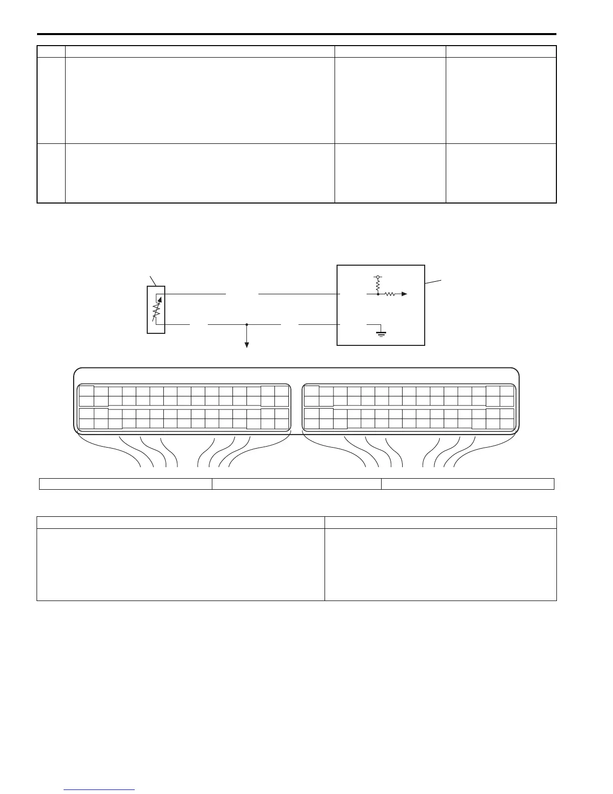
I4RS0A110025-01
1. ECT sensor 2. ECM 3. To other sensors
DTC detecting condition Trouble area
ECT sensor values is less than –5 °C, 23 °F while engine is
running under more than specified engine load (more than 1000
rpm) for 2 to 1116 min (depending on ECT at engine start)
continuously from engine start.
(*2 driving cycle detecting logic, monitoring once per driving
cycle)
• ECT sensor
• ECT sensor circuit
•Thermostat
•ECM

 Loading...


