4F-28 Electronic Stability Program:
DTC C1016: Stop Lamp Switch Circuit Failure
S7RS0B4604026
Wiring Diagram
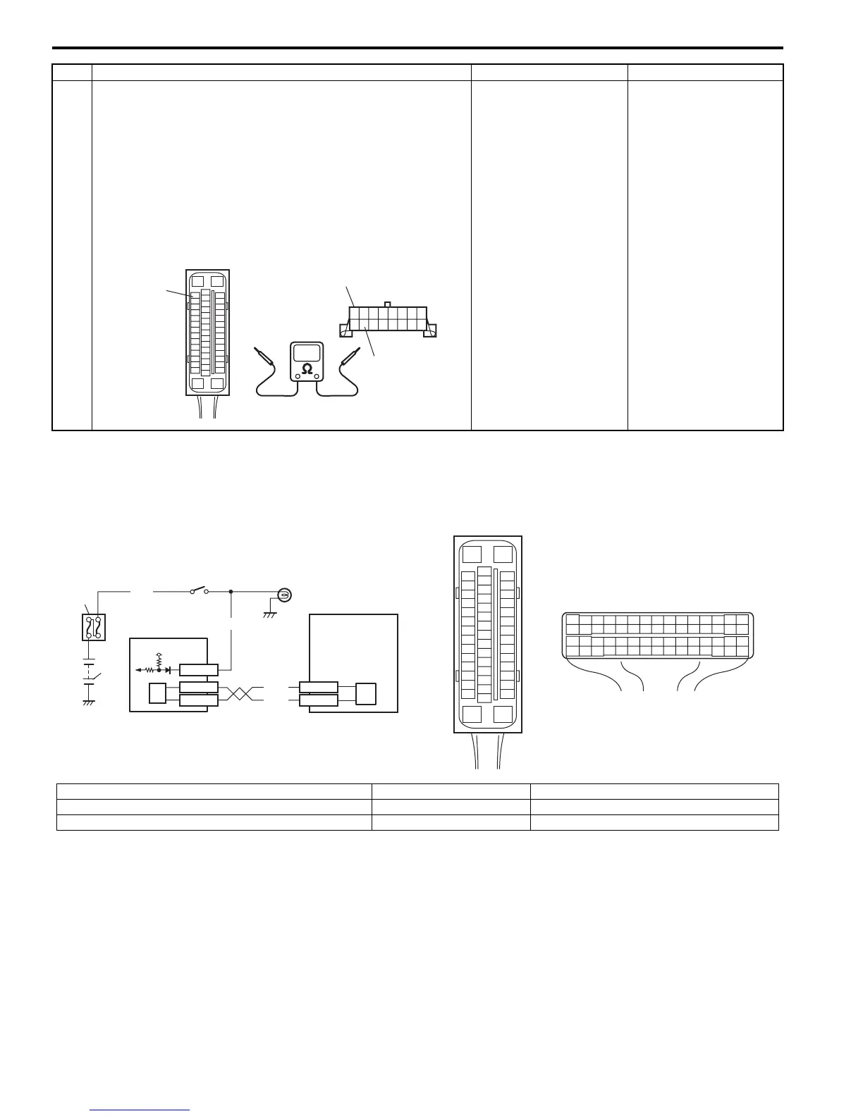
9 Check serial data circuit
1) Turn ignition switch to OFF position.
2) Check proper connection at “E85-33” (“PPL/WHT” wire)
terminal for serial data circuit.
3) If OK, then check resistance between “E85-33” (“PPL/
WHT” wire) terminal and “PPL/WHT” wire terminal (2) for
serial data circuit in DLC (1).
Is resistance 1
Ω
or less?
Substitute a known-
good ESP® hydraulic
unit / control module
and recheck.
Check high resistance
or open in “PPL/WHT”
wire circuit for electronic
stability program. If
circuit is OK, substitute
a known-good BCM and
recheck.
Step Action Yes No
“E85-33”
2
1
I6RS0B460013-01
[A]
E85
16
1
15
2
3
4
5
6
7
8
9
10
11
12
13
14
17
18
19
20
21
22
23
24
25
26
27
28
29
30
31
32
33
34
35
36
37
38
39
40
41
42
43
44
45
46
47
[B]
21
E23
34
1819
5671011
17
20
47 46
495051
2122
52
16
25
9
24
14
29
5557 5453
59
60
58
26
27
28
15
30
56
48
32 31343536374042 3938
44
45 43 41 33
1213
23
8
2
1
E85-42
E85-46
5
6
RED
WHT
4
6
7
E23-3
E23-18
12V
PNK
3
GRN/WHT
E23-20
I6RS0B460014-01
[A]: ESP® control module connector (viewed from terminal side) 3. Stop lamp switch 6. CAN driver
1. Battery 4. Stop lamp 7. ESP® hydraulic unit control module assembly
2. Main fuse box 5. ECM

 Loading...


