Electronic Stability Program: 4F-45
DTC C1073: Lost Communication With Yaw Rate / G Sensor Assembly
S7RS0B4604038
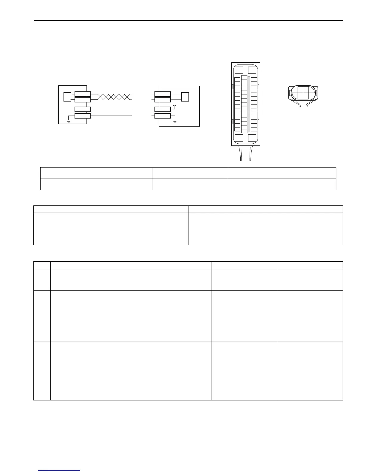
Wiring Diagram
DTC Detecting Condition and Trouble Area
DTC Troubleshooting
[A]
E85
16
1
15
2
3
4
5
6
7
8
9
10
11
12
13
14
17
18
19
20
21
22
23
24
25
26
27
28
29
30
31
32
33
34
35
36
37
38
39
40
41
42
43
44
45
46
47
E85-29
E85-25
E85-37
E85-31
E84-3
E84-5
E84-2
E84-1
12V
GRN/BLK
BLU/RED
WHT/BLK
RED/BLK
[B]
E84
3
5
21
46
1
2
3
2
I7RS0B460010-01
[A]: ESP® control module connector (viewed from
terminal side)
1. Yaw rate / G sensor assembly 3. ESP® hydraulic unit control module assembly
[B]: Yaw rate / G sensor assembly connector (viewed
from harness side)
2. CAN driver (for yaw rate / G
sensor assembly)
DTC Detecting Condition Trouble Area
CAN line communication error in ESP® control module
and yaw rate / G sensor assembly is detected.
• CAN communication circuit (for yaw rate / G sensor
assembly)
• Yaw rate / G sensor assembly
• ESP® control module
Step Action Yes No
1 Was “Electronic Stability Program Check” performed? Go to Step 2. Go to “Electronic
Stability Program
System Check”.
2 Check each control module connectors
1) Check connection of connectors of all control modules
communicating by means of CAN (for yaw rate / G
sensor assembly).
2) Check DTC for ESP®.
Is DTC C1073 detected?
Go to Step 4. Check for intermittent
trouble referring to
“Intermittent and Poor
Connection Inspection
in Section 00”.
3 CAN communication circuit check
1) Turn ignition switch to OFF position.
2) Disconnect connectors of ESP® control module and yaw
rate / G sensor assembly.
Is each CAN communication circuit between ESP
®
control
module and yaw rate / G sensor assembly opened, shorted
or high resistance?
Repair or replace the
CAN communication
line.
Go to Step 5.

 Loading...


