Home
Ricoh
Printer
MP CW2201
Ricoh MP CW2201 Service Manual
5
of 1
of 1 rating
1176 pages
Give review
Manual
Specs
To Next Page
To Next Page
To Previous Page
To Previous Page
Loading...
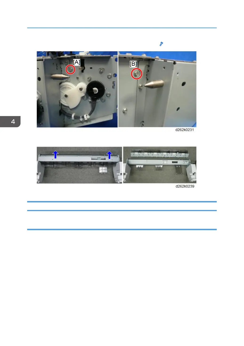
10.
Remove the screw [B] on the right of the feed roller housing (
x1).
11.
Remove the feed roller housing.
Paper Entrance Sensors, Exit Sensor
Remove
1.
Separate the feed roller housing (
p.345
,
p.348
).
4. Replacement and Adjustment
352
357
359
Table of Contents
Symbols and Trademarks
7
Symbols
7
Trademarks
8
Table of Contents
9
Product Information
31
Specifications
31
Main Machine, Peripherals, Options
32
Model Numbers and Names
32
Configuration
33
Guidance for those Who Are Familiar with Predecessor Products
35
Comparison to MP CW2201
35
Overview
36
New Features
36
Auto Nozzle Check
36
Carriage Unit
37
Ink Supply Motors
38
Carriage LED Lamp
39
New Bypass Feed
39
Manual Cut
39
Configuration
40
Locations of Major Electrical Components
41
Smart Operation Panel
42
Roll Paper Setting
44
Acronyms and Important Terms
45
Around the Machine
46
Main Sections
56
Main Components
58
Drive Layout
60
Original Path, Paper Paths
62
Installation
65
Preparation
65
Environment
65
Minimum Space Requirements
66
Configuration
67
Machine Level
67
Power Source
67
Installation Overview
68
Installation Flow
68
Main Machine Installation
70
Before You Begin
70
Accessory Boxes
70
What You Need
71
Accessory List in Box [3]
71
Accessory List in Box [5]
73
Main Unit Stand
73
Accessories: Main Unit Stand
73
Installing the Main Unit Stand
74
Mounting the Main Unit
76
Assembling the Scanner Stand
81
Accessories: Scanner Stand
81
Installing the Scanner Stand
82
Mounting the Scanner Unit
84
Roll Unit 1 (Standard)
87
Accessories: Roll Unit 1
87
Installing Roll Unit 1
88
Wiring Roll Unit 1
94
Roll Unit 2 (Option)
97
Accessories
98
Installing Roll Unit 2
99
Wiring Roll Unit 2
102
Controller Options
109
Connecting the Scanner and Main Unit
109
Parts to be Used
109
Connecting the Harnesses
110
Wiring the Scanner Cable
112
Clamping the Power Cord
117
Removing Tapes and Shipping Materials
119
Original Stacker, Guides
121
Installing the Original Stacker, Guides
121
Ink Collector Tank Storage Shelf
123
Installing the Ink Collector Tank Storage Shelf
123
Exit Stacker
125
Accessories: Exit Stacker
125
Installing the Exit Stacker
125
Changing the Mode of the Paper Exit Stacker
131
Ink Filling
132
Draining and Filling Procedure
132
If Draining Fails to Start
135
Setting Roll Paper
136
Setting the Paper Spool to Roll Paper
136
Setting the Paper Roll to the Machine
138
Connecting to the Gigabit Ethernet Interface
141
Check Printing
143
Nozzle Check Pattern
143
When an Unbroken Nozzle Check Pattern Cannot be Produced
145
Halftone Check
145
Final Adjustments
146
Caster Lock
146
Level Adjustment
147
Manual Adjust Head Position
148
Adjust Paper Feed
150
Adjust Print Position
151
Final Settings
152
After Installation
153
Moving the Machine
153
Controller Options
154
Overview
154
Slots
154
Standard Controller Features
155
SD Card Appli Move
155
Overview
155
Move Exec
155
Undo Exec
156
IEEE 802.11 A/G/N Interface Unit Type M19
157
Included Parts
158
Installation
158
Attaching Antennas
159
Checking the Wireless LAN Interface Connection
164
OCR Unit Type M13
165
Recovery Procedure
168
File Format Converter Type M23 (MLB)
169
Included Parts
169
Installation of MLB
169
Data Overwrite Security Unit Type M19
171
Overview
171
Before You Begin the Procedure
171
Seal Check and Removal
172
Installation Procedure
172
R/W NFC Personal Authentication IC Card
174
Included Parts
174
Installation Guide
175
Check All Connections
181
Security Setting
182
Security Function Installation
182
Data Overwrite Security
183
Before You Begin the Procedure
183
Using Auto Erase Memory
183
HDD Encryption
185
Before You Begin the Procedure
185
Enable Encryption Setting
185
Backing up the Encryption Key
188
Encryption Key Restoration
188
Remote Setting
191
Settings Relevant to the Service Contract
191
Settings for @Remote Service
191
Preventive Maintenance
197
Preventive Maintenance Tables
197
PM Cleaning Points
198
PM Table
198
Scanner Unit
198
Horizontal Unit
201
Waste Ink Collection
205
Other Items for Cleaning
209
External Covers
209
Scanner Unit
210
Horizontal Unit
212
Paper Feed
212
Roll Units
214
Replacement and Adjustment
219
Notes on the Main Power Switch
219
Push Switch
219
Characteristics of the Push Switch (DC Switch)
219
Shutdown Method
220
Forced Shutdown
222
General Precautions
223
External Covers
223
Original Transport
223
Paper
225
Copy Quality
225
Cis
226
Electrical Components
226
Adjustments at Machine Installation
226
Other Precautions
226
Service Precautions
227
Scanner Unit Rollers
227
Main Frame Screws
228
Right Plate Screws
228
Maintenance Unit Base Screws
229
Solenoid Bracket Screw
230
Main Carriage Screws
231
Temperature/Humidity Sensor Bracket
231
Notes on Operation of the Paper Holding Lever
232
Common Procedures
234
Before You Begin
234
Before Servicing the Machine
235
Rear Output Guides
235
Original Guides
236
Original Stacker
236
Ink Collector Tank
238
Paper Rolls
238
Main Covers
239
Left Cover
240
Right Cover
245
Right Upper Cover
247
Ink Cartridge Cover
249
Top Cover
251
Right Rear Cover
253
Left Rear Cover
254
Front Cover
255
Paper Exit Guide
257
Scanner Unit
260
Raise the Scanner Unit Fully
260
Scanner Upper Cover
261
Scanner Rear Cover
266
Scanner Left Cover, Scanner Right Cover
266
Original Table
267
Raise the Left Side of the Scanner Unit
268
Raise the Right Side of the Scanner Unit
270
Moving the Carriage Unit
273
Before You Begin
273
Move the Carriage Unit with SP2-102-4
273
Uncapping the Print Heads and Moving the Carriage Unit Manually
275
Capping the Print Heads Manually
279
Disconnecting the Main Unit from the Scanner Unit
280
Disconnecting the Scanner Cable
281
Separating the Main Unit from the Scanner Unit
284
Operation Panel
285
Remove
285
Precaution
287
Scanner
290
Before You Begin
290
Safety Switch Diagram
290
Original Width Sensors, Original Set Sensor
291
Safety Switch
294
Original Registration Sensor
295
Scanner Motor
296
SIB (Scanner I/F Board)
298
Remove
298
Precaution
299
Original Feed Roller
300
Remove
300
Adjustment
304
Exposure Glass
305
Remove
305
Precaution
306
CIS Unit
307
Remove
307
Precaution
309
Adjustment
311
Original Exit Sensor
311
Original Exit Roller
312
Remove
312
Adjustment
316
White Plate Bracket
316
Original Stop Switch
317
Roll Units
320
Roll Unit 1
320
Remove
320
Precaution
326
Roll Unit 2 (Option)
328
Remove
328
Precaution
333
Rewind Switch
335
Remove
335
Precaution
336
Left Outer Cover, Left Inner Cover
336
Remove
336
Precaution
337
Encoder Sensors
338
Remove
338
Cleaning
339
Roll Paper Feed Motor
340
Roll Paper Feed Clutch
342
Remove
342
Precaution
346
Paper Release Sensor
348
Remove
348
Cleaning
349
Precaution
350
Feed Roller Housing
350
Separate the Feed Roller Housing (Roller Unit 1)
351
Separate the Feed Roller Housing (Roller Unit 2)
354
Paper Entrance Sensors, Exit Sensor
358
Remove
358
Cleaning
361
Feed Roller
361
Remove
361
Precaution
364
Roll End Sensor
364
Paper Transport
367
Bypass Sensor
367
Pre-Registration Sensor
368
Registration End Sensor
369
Paper Transport Fan Motor
370
Paper Exit
372
Cutter
372
Exit Guide
373
Remove
373
Precaution
374
Cutter Unit
375
Cutter Switch (Right)
378
Cutter Switch (Left)
379
Cutter Motor
380
Motor Timing Belt, Cutter Belt
381
Remove
381
Precaution
384
Paper Exit Sensor
385
Guide Plate Safety Sensor
386
Main Scan
388
Horizontal Encoder Sensor
388
Remove
388
Precaution
390
Horizontal Encoder Sheet
391
Remove
391
Cleaning
394
Precaution
394
Horizontal Motor
395
Horizontal Timing Belt
397
Sub Scan
399
Vertical Encoder Sensor
399
Precaution
400
Vertical Encoder Wheel, Timing Belt
400
Vertical Encoder HP Sensor
403
Vertical Motor
405
Bypass Stopper Clutch Sensor
406
Bypass Stopper Clutch
408
Carriage Unit
412
Before You Begin
412
DRESS Sensor
413
Remove
414
Cleaning
416
Adjustment
417
Led
420
Remove
420
HRB (Head Relay Board)
422
Remove
422
Precaution
429
Head Lift Motor
429
Print Head Unit
431
Black Print Head Unit Accessories
432
Color Print Head Unit Accessories
433
Carriage Unit Cover Removal
433
Black Print Head Unit Removal
435
New Black Print Head Unit Installation
443
Color Print Head Unit Removal
452
New Color Print Head Unit Installation
460
After the Print Head Unit Replacement
468
Carriage Unit
471
Remove Ink Supply Unit
472
Free the Harness on the Right Side of the Main Unit
475
Main Ink Level Sensor Bracket Removal
480
Ink Tube Rail Removal
482
Horizontal Encoder Sheet Removal
483
Tension Bracket Removal
485
Right Plate Removal
487
Carriage Unit Removal
492
Precaution
504
Ink Supply
510
Ink Supply Unit
510
Ink Supply Unit Accessories
510
Before You Begin
511
Ink Supply Unit Replacement
511
Carriage Disconnection
512
Ink Supply Unit Removal
520
New Ink Supply Unit Installation
520
Ink Tube Attachment to the Print Head Unit
522
Air Release Solenoid
527
Ink Level Sensor and Temperature/Humidity Sensor
531
Maintenance Unit, Waste Ink Collection
536
Left Ink Sump
536
Ink Collector Unit
537
Ink Collector Unit Contact Switch
538
Right Ink Sump
539
Maintenance Unit
540
Auto-Nozzle Check
544
Auto-Nozzle Check Upper Unit
544
Auto-Nozzle Check Unit
546
After Replacement
548
Electrical Components
550
Rear Cover
550
PCB Box
551
Controller Board
559
Remove
559
Replacing the NVRAM and Memory
561
RFDB (Roll Feeder Drive Board)
562
Remove
562
IOB (Input/Output Board)
564
Remove
564
Hdd
566
Remove
566
Settings
567
Bicu (Base Image Control Unit)
568
Remove
569
EEPROM Replacement
570
Nvram
572
NVRAM on the Controller Board
572
NVRAM (EEPROM) on the Bicu
574
PSU (Power Supply Unit)
576
Remove
577
Precaution
578
Sensors, Switches
579
Ink Collector Tank Cover Switch
579
Ink-Cartridge Cover Switch
579
Front Cover Safety Switches
580
Front Cover Switch
581
Remove
581
Precaution
583
Special Adjustments
584
Image Adjustment with SP Modes
584
Step 1: Magnification for Paper Type: Plain
584
Step 2: Copy/Main Scan Magnification
585
Step 3: Copy/Print Sub Scan Magnification
585
Step 4: Scanner Mask Setting
586
Step 5: Erase Margins
587
Step 6: Printer: Leading Edge, Side-To-Side Registration
587
Step 7: Scanner Mask Setting
588
Step 8: Erase Margins
589
Step 9: Scanner Registration
589
Step 10: Printer: Cut Length
590
Step 11: Synchro Cut (Trailing Edge Registration)
591
CIS Adjustment with SP Modes
592
To Print the CIS Adjustment Pattern
592
To Adjust the Image at the CIS Joints
593
To Adjust the Scan Speed Switching
594
System Maintenance Reference
597
Service Program Mode
597
Firmware Update
598
Overview
598
Firmware Type
598
Procedure
600
Update Procedure
600
Error Screens During Updating
605
RFU Updating the Firmware
612
RFU Performable Condition
612
Package Firmware Update
613
Overview
613
Immediate Update
614
Update at the Next Visit (Reserve)
617
How to Set the Machine to Download Firmware Later (RESERVE)
617
How to Check if the Firmware Downloaded with RESERVE
619
How to Install Firmware Downloaded with RESERVE
621
Update Via SD Card
624
Updating Javavm
627
Creating an SD Card for Updating
627
Updating Procedure
627
List of Error Messages
628
Capturing the Debug Logs
630
Overview
630
Security of the Operation Log
632
Retrieving the Debug Logs
632
Procedure for Retrieving the Debug Log with SD Card
632
Reboot/System Setting Reset
634
System Settings and Copy Setting Reset
634
System Setting Reset
634
Copier Setting Reset
634
NVRAM Data Upload/Download
636
Uploading Content of NVRAM to an SD Card
636
Downloading an SD Card to NVRAM
637
Address Book Upload/Download
639
Information List
639
Download
639
Upload
641
SMC List Card Save Function
642
Overview
642
SMC List Card Save
642
Procedure
642
File Names of the Saved SMC Lists
644
Error Messages
645
UP/SP Data Import/Export
646
Overview
646
Import/Export Conditions
646
UP Data Import/Export
646
Data that Can be Imported and Exported
646
Data that Cannot be Imported or Exported
646
Exporting Device Information
647
Importing Device Information
649
SP Data Import/Export
650
Data that Can be Imported and Exported
650
Exporting Device Information
650
Importing Device Information
651
Possible Solutions for Import/Export Problems
652
Test Pattern Printing
655
Card Save Function
656
Overview
656
Card Save
656
Procedure
656
Error Messages
659
Troubleshooting
661
Service Call Conditions
661
SC100: Scanning
662
SC200: Image Writing
667
SC300: Not Used
685
SC400: Not Used
686
SC500: Paper Feed, Transport
687
SC600: Communication
696
SC700: Not Used
712
SC800: Firmware
713
SC900: Software
724
Printing Problems
728
Before You Begin
728
White Lines, Horizontal Banding
728
Print Heads Clogged
728
Other Measures
729
Horizontal Lines in Margins
729
White, Color Vertical Banding
730
Print Head out of Position, Horizontal Encoder Strip Problem
730
Overall Poor Image Quality
730
Gap Adjustment
731
Print Heads Clogged
731
Paper Feed Faulty
731
Horizontal Encoder Strip
731
Text Shifted out of Position
732
Obstructed, Faulty Paper Feed
732
Ink Scatter
733
Gap Adjustment
733
Print Heads Clogged
733
Faulty Maintenance Unit, Carriage Unit
734
Mixed Colors
734
Print Heads Clogged
734
Faulty Maintenance Unit
735
Image Abraded, Paper Torn, Ink Running
735
Gap Adjustment
735
Paper Feed Obstruction
735
Faulty Carriage Unit
736
Color Density too Light
736
Printer Driver Settings
736
Part of Image Missing, Text Misaligned
736
Printer Driver Settings
737
Faulty Controller
737
Image Skewed on Paper
737
Obstructed Paper Feed
737
Bolded Text Does Not Appear Bold in Printout
737
Printer Driver Settings
738
Scanning Problems
739
Flow Chart
739
Scanning Troubleshooting
739
Jam Code Tables
744
Overview
744
Scanner Original Jams
745
Printer Paper Jams
746
Electrical Components
750
Scanner Unit
750
Main Unit Sensors, Motors
751
Roll Units
754
Ink Supply
756
Carriage Unit
757
Around the Carriage Unit
760
Maintenance Unit
761
Boards
763
Fuses
765
Scanner Unit
765
Operation Panel
765
SIB (Scanner I/F Board)
765
Main Boards (PCB Box)
766
Controller Board
766
IOB (Input/Output Board)
768
Bicu (Base Image Control Unit)
770
PSU (Power Supply Unit)
773
Carriage Unit
774
Hrb
774
Detailed Description
777
Overview
777
General Operation Sequence
777
Power on
777
Paper Exit and Job End
778
Scanner Unit
779
Scanner Layout
779
Side View
779
Front View
780
Original Width Detection
781
Scanning
783
Original Feed, Exit Sequence
783
Auto Image Density Correction
784
Scanning Area
785
Scan Magnification Correction
785
Original Drive Mechanism
786
Scanning Motor, Rollers
786
Original Feed Speed
787
Scanning Mechanism
788
CIS Structure
788
Printed Image
789
Long Original or Special Original with Carrier Sheet
789
Related Sps
790
Image Processing
791
Features for Printing
791
Image Flow
792
Copy Job Image Data Flow
792
Scan Job Image Data Flow
793
Print Job Image Data Flow
794
Copy Mode Image Processing
794
Print Mode Image Processing
795
Copy Resolution: Copy Jobs and Print Jobs
795
Copy Jobs
796
Print Jobs
797
Image Troubleshooting
800
Paper Feed and Exit
803
Overview
803
Roll Unit Operation
804
General Operation of Roll Unit
804
Roll Feed Mechanism
805
Initializing the First Paper Roll
806
Initializing the Second Paper Roll
810
Roll Rewinding for Removal
810
Roll End
813
Main Unit Paper Feed
814
Registration Roller
814
Vertical Feed Mechanism
815
Remaining Paper Detection
817
Paper Transport Fan
820
General Operation
820
Transport Fan Duty Adjustment
821
Normal Paper, Recycled Paper
822
Translucent Paper
823
Front Cover Switches
824
Detailed Description of Paper Feed Sequence
825
Paper Feed Layout
825
Operation Sequence When the First Roll Is Set
826
Operation Sequence When the Second Roll Is Set
828
Cutting
828
Manual Cut
829
Bypass Feed
830
Related Sps
832
Ink Supply
833
Overview
833
Ink Cartridge
835
Ink Supply Mechanism
837
Controlling Ink Supply to the Sub Tanks
839
The OCFS System
839
Controlling Ink Supply During Printing
841
Air Detection and Air Purging
841
Air Purge Mechanism
842
After Air Purging
843
Emergency Print
843
Printable Conditions
844
Printing
844
Conditions for Function End
844
Number of Printable Sheets
844
Operation of Emergency Print
845
Printing
846
Printing Drive Mechanism
846
Carriage Unit
847
Print Head Unit
851
Print Head
852
DRESS Sensor
853
Temperature Monitoring
856
Print Head Height Adjustment
857
Height Adjustment Mechanism
858
Raising and Lowering the Print Heads
859
Maintenance Unit
860
Overview
860
Capping/Uncapping
861
Print Head Cleaning Cycle
863
Manual Print Head Cleaning and Flushing
867
Automatic Downtime Cleaning
868
Automatic Mist Cleaning
869
Auto-Nozzle Check Module
870
Overview
870
Timing for Detection
871
Detection
871
Wiping an Electrode Plate
872
When Ink Deficiency Is Detected
874
Operating Life
876
Waste Ink Collection
876
Ink Collector Tank
877
Right Ink Sump
878
Left Ink Sump
879
Related Sps
880
Print Head Cleaning and Adjustment
882
Nozzle Check Pattern Print
882
Clean Print Heads
883
Flush Print Heads
884
Adjust Head Position
885
Automatic Adjust Head Position
885
Manual Adjust Head Position
886
Adjust Paper Feed
887
Adjust Print Position
889
Prevent Paper Abrasion
891
Electrical Components
893
Boards
893
Block Diagram
893
Parts Layout
894
SIB (Scanner I/F Board)
894
Controller Board
895
IOB (Input/Output Board)
897
Hdd
897
Bicu (Base Image Control Unit)
898
PSU (Power Supply Unit)
899
File Format Converter Type M23 (MLB)
900
Energy Save
902
Energy Save Mode
902
Specification
903
SP2-XXX Scanning Image Quality
1170
Input and Output Check
1172
Input Check Table (SP5-803)
1172
Output Check Table (SP5-804)
1175
5
Based on 1 rating
Ask a question
Give review
Questions and Answers:
Need help?
Do you have a question about the Ricoh MP CW2201 and is the answer not in the manual?
Ask a question
Ricoh MP CW2201 Specifications
General
Brand
Ricoh
Model
MP CW2201
Category
Printer
Language
English
Related product manuals
Ricoh MP CW2200SP
220 pages
Ricoh MP C307
1241 pages
Ricoh MP C407
1241 pages
Ricoh MP C6502SP
28 pages
Ricoh MP C306 series
64 pages
Ricoh MP C406 series
64 pages
Ricoh Aficio MP C4501
256 pages
Ricoh Acifio MP C3002
6 pages
Ricoh Aficio MP C4501 Series
94 pages
Ricoh Aficio MP 2000
132 pages
Ricoh Aficio MP 4000
1118 pages
Ricoh Aficio MP 3500/MP 4500
6 pages