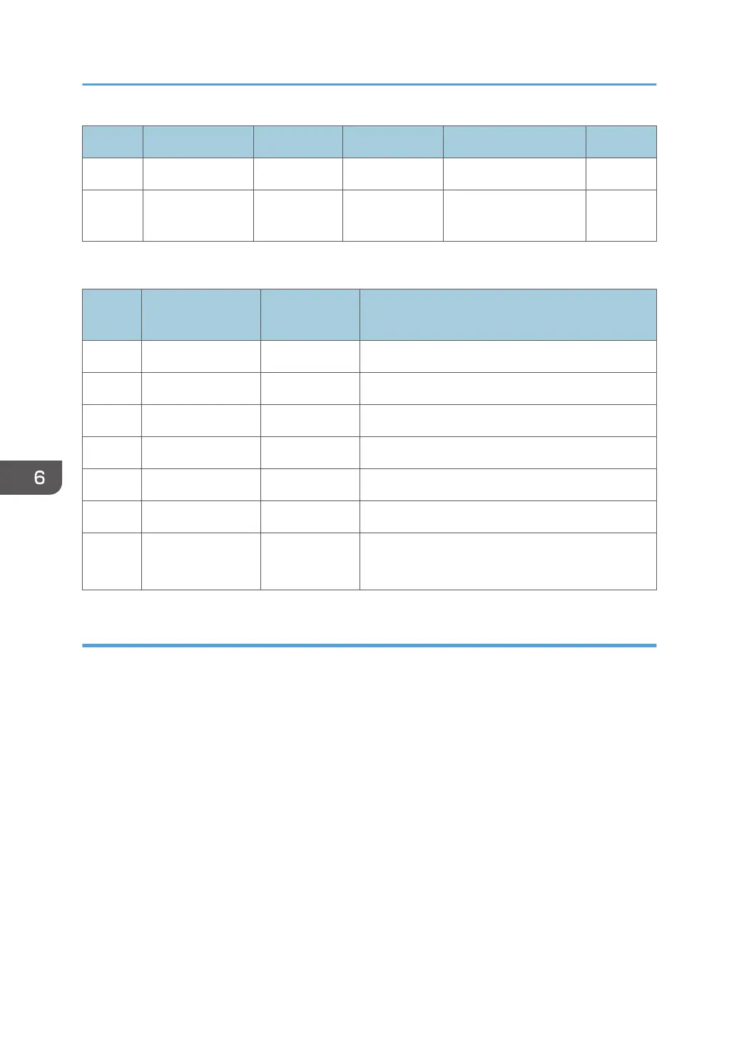
Name Output terminal Capacity Voltage Type Part No.
FU7 CN256 - 24V SIB -
FU8
CN251, 252,
253
- 24V Key Counter, Key Card -
SW1
SW No. Note
Settings at
Installation
Note
1 - OFF Prohibited
2 - OFF Prohibited
3 - OFF Prohibited
4 - OFF Prohibited
5 - OFF Prohibited
6 - OFF Prohibited
8 Ri debug mode OFF
OFF: Normal
ON: IC20 debug mode
BiCU (Base image Control Unit)
The BiCU is placed at the back of the IOB in the PCB box.
The control board controls the system, base engine, and scanner, sends the load signal of the base
engine (high-voltage power supply, motors, sensors, solenoids, and clutches) and scanner (sensor and
motor), and supplies power as IO.
This also performs image processing. After processing image data sent from the CIS, this sends the
processed data to the head through IOB and HRB.
6. Troubleshooting
764
 Loading...
