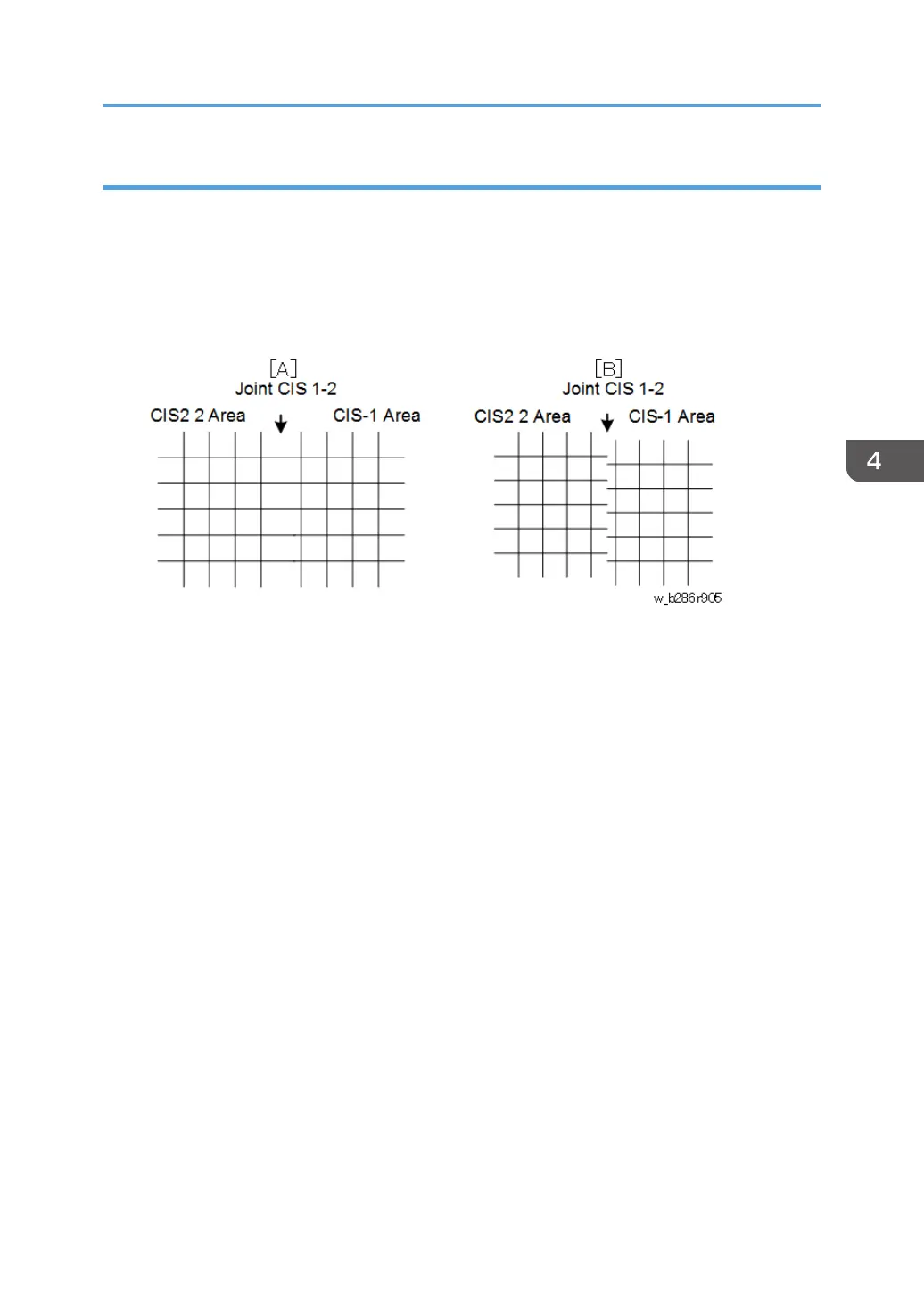
To Adjust the Image at the CIS Joints
1. Check the printed pattern to determine if the dots are aligned at CIS 1-2.
2. If they are aligned correctly, no adjustment is necessary.
-or-
If they are not aligned correctly, do the next step. Here are two samples where the outputs are not
aligned correctly.
• [A]: Distance between the lines at CIS 1-2 is wider than usual (as shown above). If the
distance between these lines is wider or narrower than the other lines, adjust the main scan
offset at CIS 1-2 with SP4-972-001 (CIS Joint Adjustment –CIS 1-2 Main Scan) as described
below.
• [B]: The lines at CIS 1-2 are broken. If the output from CIS 1 is lower (as shown above) or
higher, adjust the sub scan offset at CIS 1-2 with SP4-972-006 (CIS Joint Adjustment – CIS
1-2 Sub Scan) as described below.
To adjust the main scan offset for Example [A]
Problem: Output from CIS 1 is too far to the right.
1. Do SP4-972-001 and adjust the setting.
• Adjust the position of CIS 1. The position of CIS 2 does not move.
• If the area at the joint is too wide, set a smaller value.
• If the area at the joint is too narrow, set a larger value.
• In the example [A], you must set a smaller value.
To adjust the sub scan offset for Example [B]
Problem: Output from CIS 1 is lower than the output from CIS 2.
1. Do SP4-972-006 and adjust the setting.
• Adjust the position of CIS 1. The position of CIS 2 does not move.
• If the CIS 1 area is higher than the CIS 2 area, set a larger value.
Special Adjustments
587
 Loading...