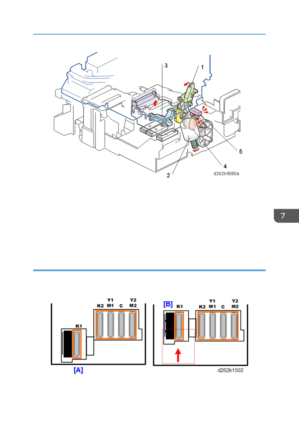
• At the end of a print job, the carriage unit moves to the right and positions itself over the
maintenance unit.
• The carriage stopper (1) positions the carriage unit so that the caps and print heads are aligned.
• The maintenance lift motor (2), rotating forward, raises the K2, C, Y,M print head caps (not shown)
on the lift lever (3) and covers the print heads to prevent them from drying out.
• The rotating lift actuator (4) (mounted on a shaft with a lift cam driven by the lift motor) and lift
sensor (5) control the raising of the caps.
Print Head Cleaning Cycle
The four steps of the cleaning cycle are done for each print head that requires cleaning.
Step 1: Sliding the Cleaning Unit to the Rear
This step moves the cleaning unit from [A] to [B] in order to clean the K2, C, and YM print heads.
Printing
857
 Loading...