Component Removal
SM 3-19 J007/J010/J011
J007/J010/
J011
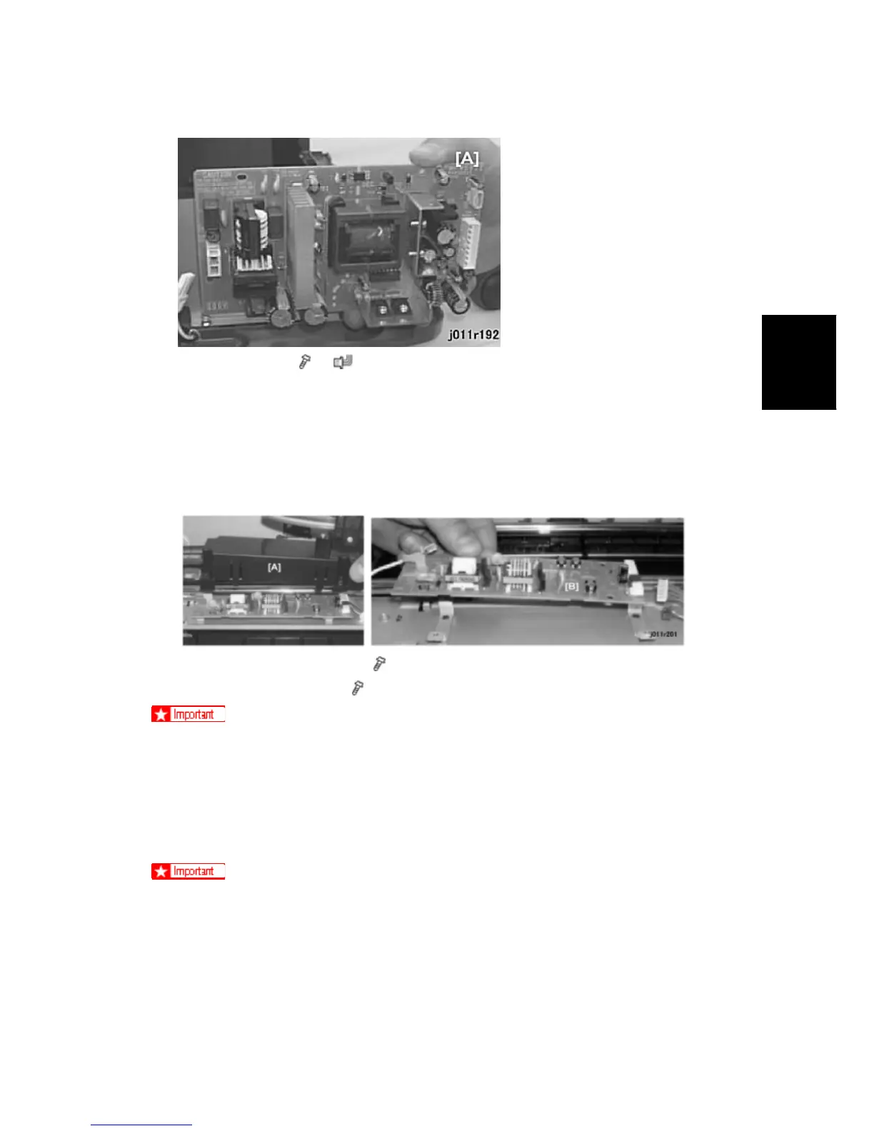
4. Remove the PSU (
x4, x1)
3.4.4 HIGH VOLTAGE POWER SUPPLY BOARD
Remove:
Right cover
Top cover
Front cover
1. Remove the HVPS cover [A] (
x4, (x4)
2. Remove the HVPS board (
x3)
Press up gently as you pull if the bayonet is difficult to disconnect
3.4.5 MAIN CONTROL BOARD
Before replacing the control board and NVRAM together, you should always print a
System Summary, Service Summary, and Engine Summary Chart. You will need these
reports to do important settings after replacement.
You will need these printouts to reference previous settings that may require
resetting.
To print the System Summary:
Confirm that paper is loaded in the paper tray.
Push [Menu].

 Loading...